Week 9 - Challenge 1 - Base Bracket Design
Aim: Create the Base Bracket Plastic component through the given Class-A surface. To begin with, the tooling axis for the given Class A Surface should be created meeting the requirements of the draft angle and at the end perform the Draft analysis on the model.
STEP 1:
- Check the connectivity of the Class A Surface
- Ensure that there is no gap between the component, using the join command
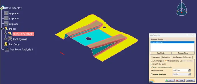
TOOLING AXIS:
Tooling axis or Molding axis is the direction in which the core and cavity opens. It is basically the direction that the mold pulls apart. Creating a tooling axis is necessary to provide draft angle and analysis them. The tooling axis is created using Bisecting method.
STEP 2: Creating the Tooling Axis in Given part.
- Check visually which is the best possible tooling axis.
- Check all three axes.
Y-Axis
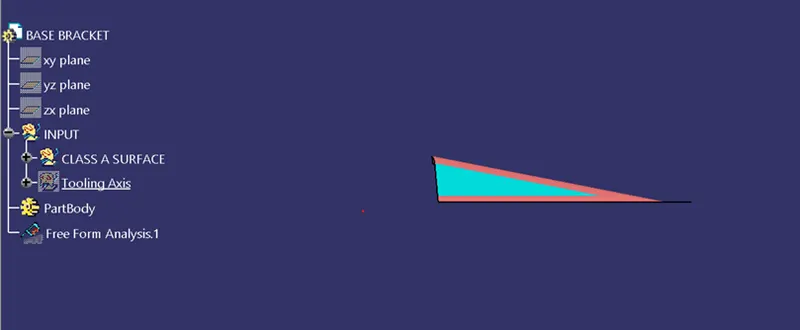
X-Axis
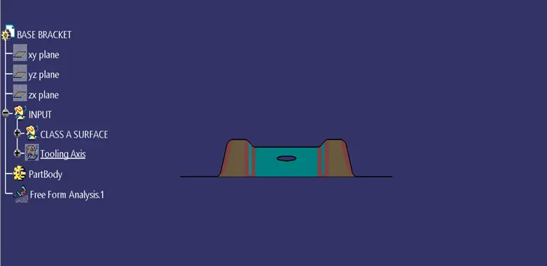
Z-axis
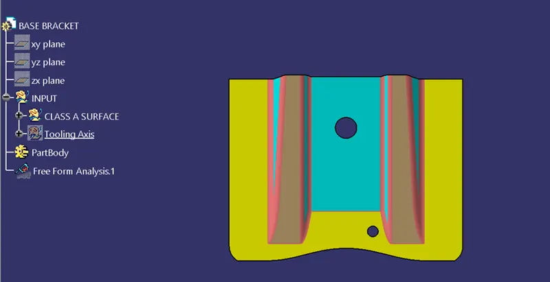
- z is the best possible tooling axis.
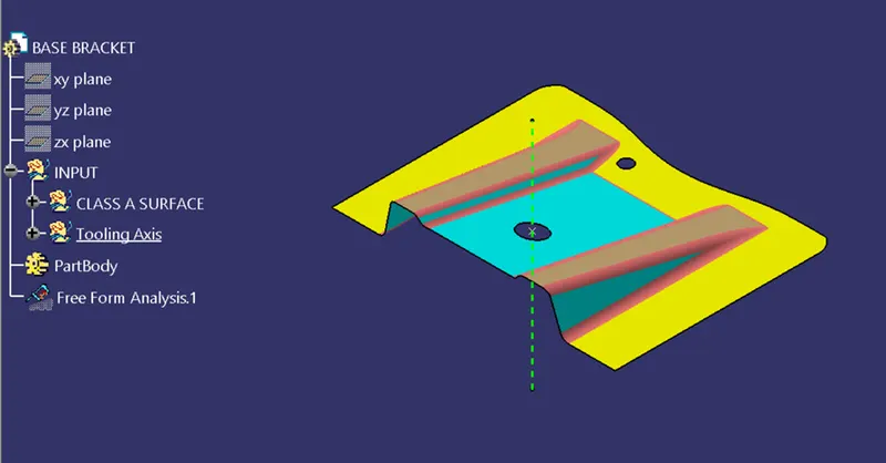
BISECTING METHOD:
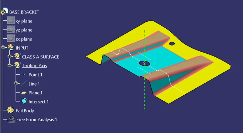
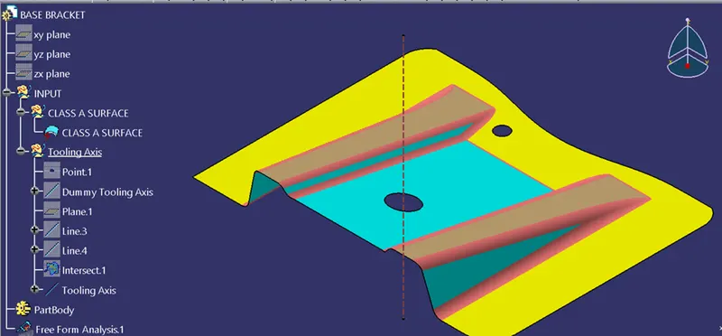
Now creating Class B Surface:
CLASS-A surface:
- A surface made by the designer which is given as an input to the plastic modeler to work on. It is aesthetic surface and the outer most surface.
- It is aesthetic surface
CLASS-B surface:
- A surface below a certain thickness from the class-A surface is class-B surface.
- This is the surface that contains engineering aspects of a model.
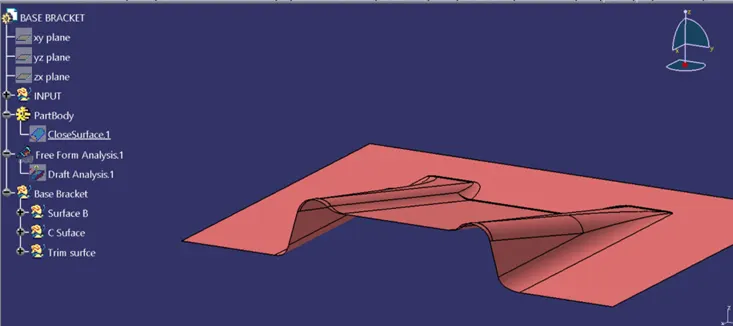
SurFace B:
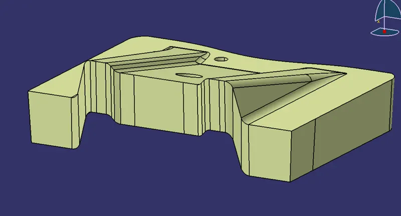
SurFace C:
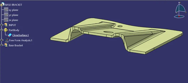
Final Part:
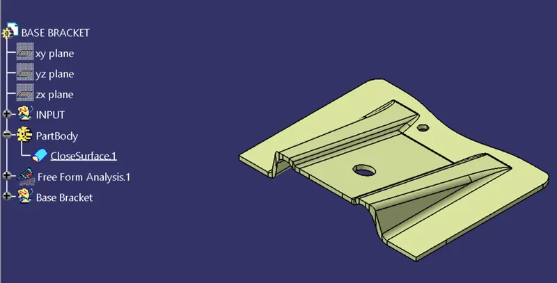
Isometric View:
Front View:
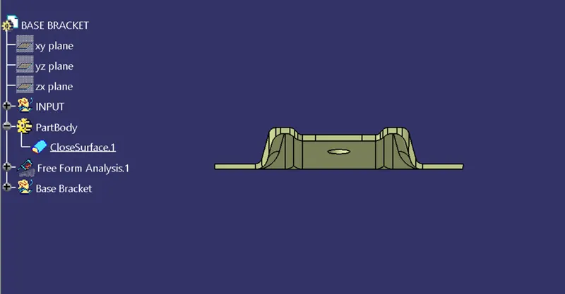
Top View:
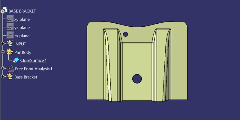
Draft analysis
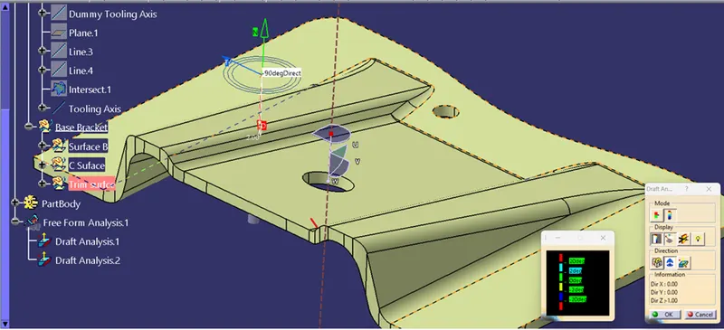
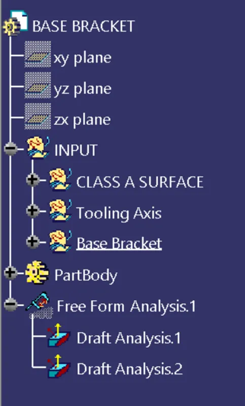
Tree Stucture: