Week 9 - Challenge 1 - Base Bracket Design
Objective :
To Create B-class surface, C-class surface, and the tooling axis for the given Base bracket model.
To publish class-A surface, B-class surface, C-class surface, and the tooling axis
Performing draft analysis to verify the creation of the Tooling axis.
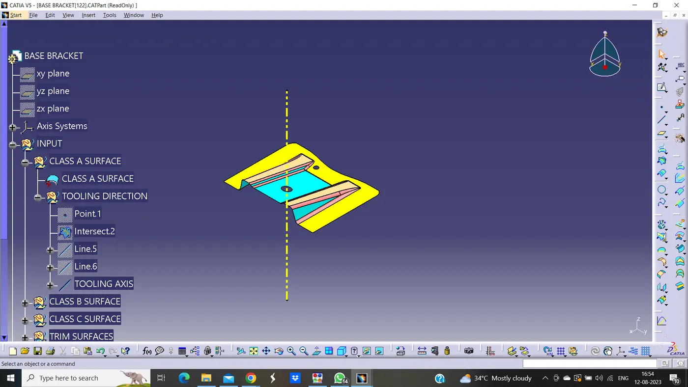
A-Class Surface
A-Class surface is a term used in plastic product design. That means the surface of a component that is smooth( aesthetic) or visible side to the human eye after the part is assembled. it refers to those surfaces which are visible and abide by the physical meaning of a product.
B-Class Surface
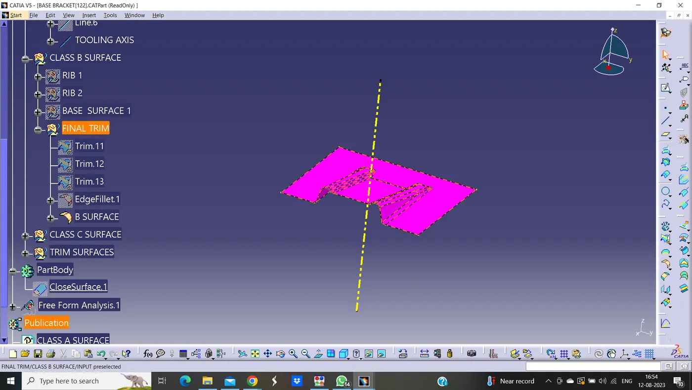
B-Class surfaces are the secondary surfaces that you can see sometimes, but are less important, such as the inside of your glove box, ashtray, etc... These must be smooth and "error-free" as well but are not held to the standards that class A surfaces are. it also means the thickness of a part.
C-Class Surface
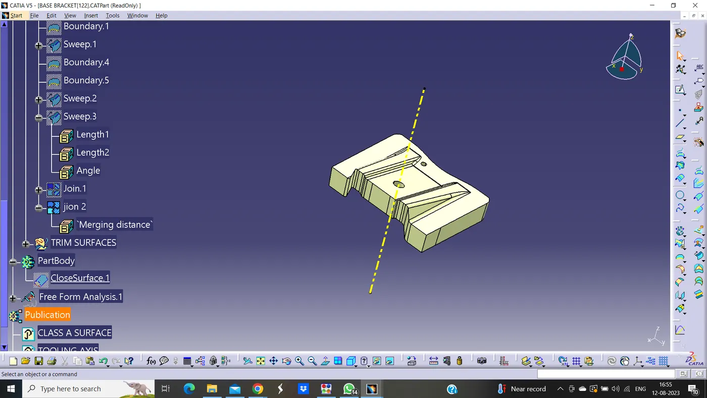
C-class surfaces are the backside surfaces that can have tool marks, flash, and other imperfections without hurting appearance, function, etc...it also means A and B combined to give C surface.
CLOSE SURFACE
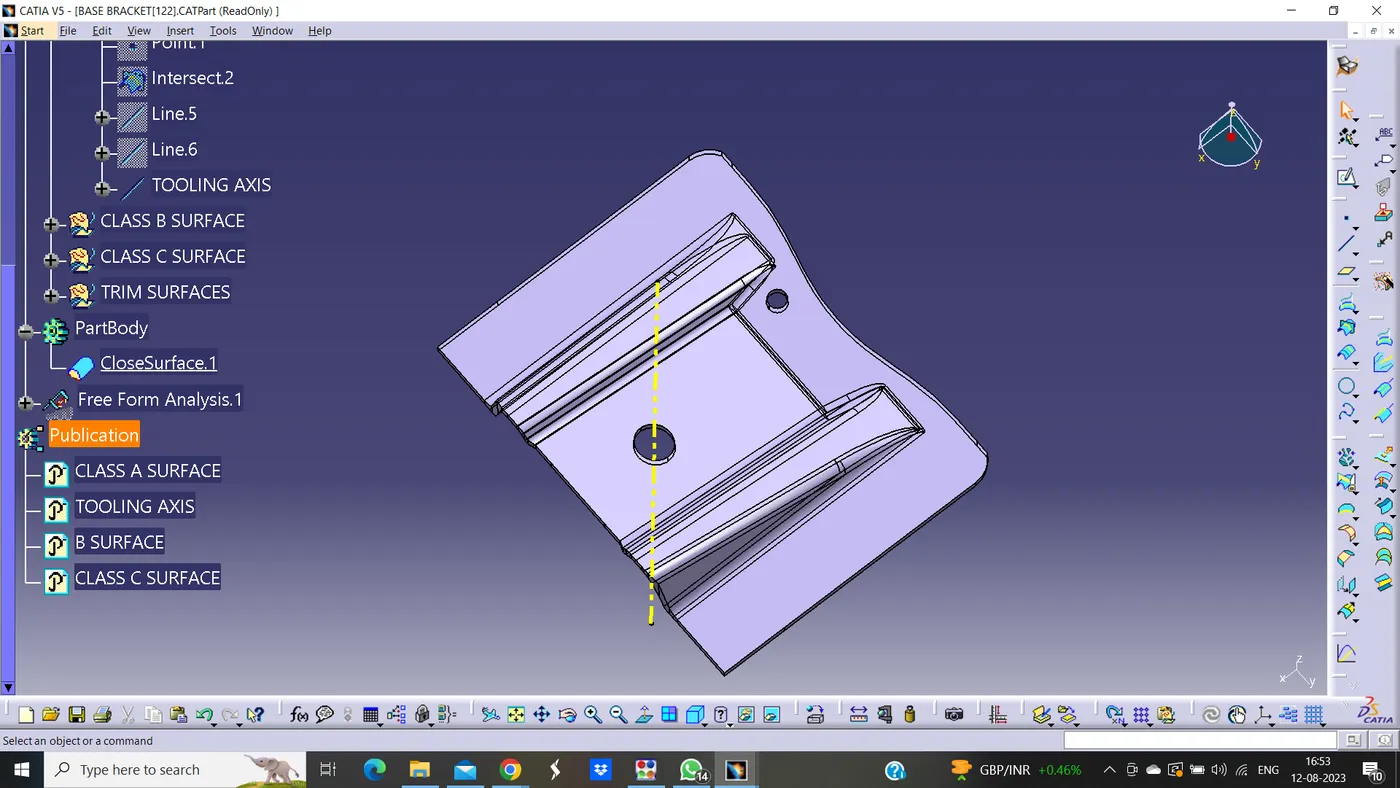
Using the closed surface option created a solid part of the base bracket
Procedure for design A-Class, B-Class, and C-Class of Base Bracket :
Extract Rib then untrim, Extrapolate and trim the base bracket.
Extract 2nd rib same as rib 1.
offset rib 1 and rib 2 by 2.5mm.
Extract and offset both the supportive base surface.
Provide untrim and extrapolate and offset by 2.5mm.
Apply Fillet and Rename as B-Class surface.
Swept A-class Surface to the 3-degree downside with draft direction.
Join swept and A-Class Surface then trim with B-class surface.
Change into the close body for appropriate output.
Procedure for Features Draft Analysis
Before performing the draft analysis we create the Main tooling axis then the procedure.
{Go to menu bar > select insert > Analysis > Feature Draft Analysis} .
Now, align the compass z-direction with the main tooling axis which we created in the previous steps.
Now, open the color scale and enter the value as 3 deg.
Now hover the cursor over the body to check if every face has an angle greater than the given angle.
Also, if the whole body is in green color it means that the value at all the faces is greater than the provided angle.
Publication
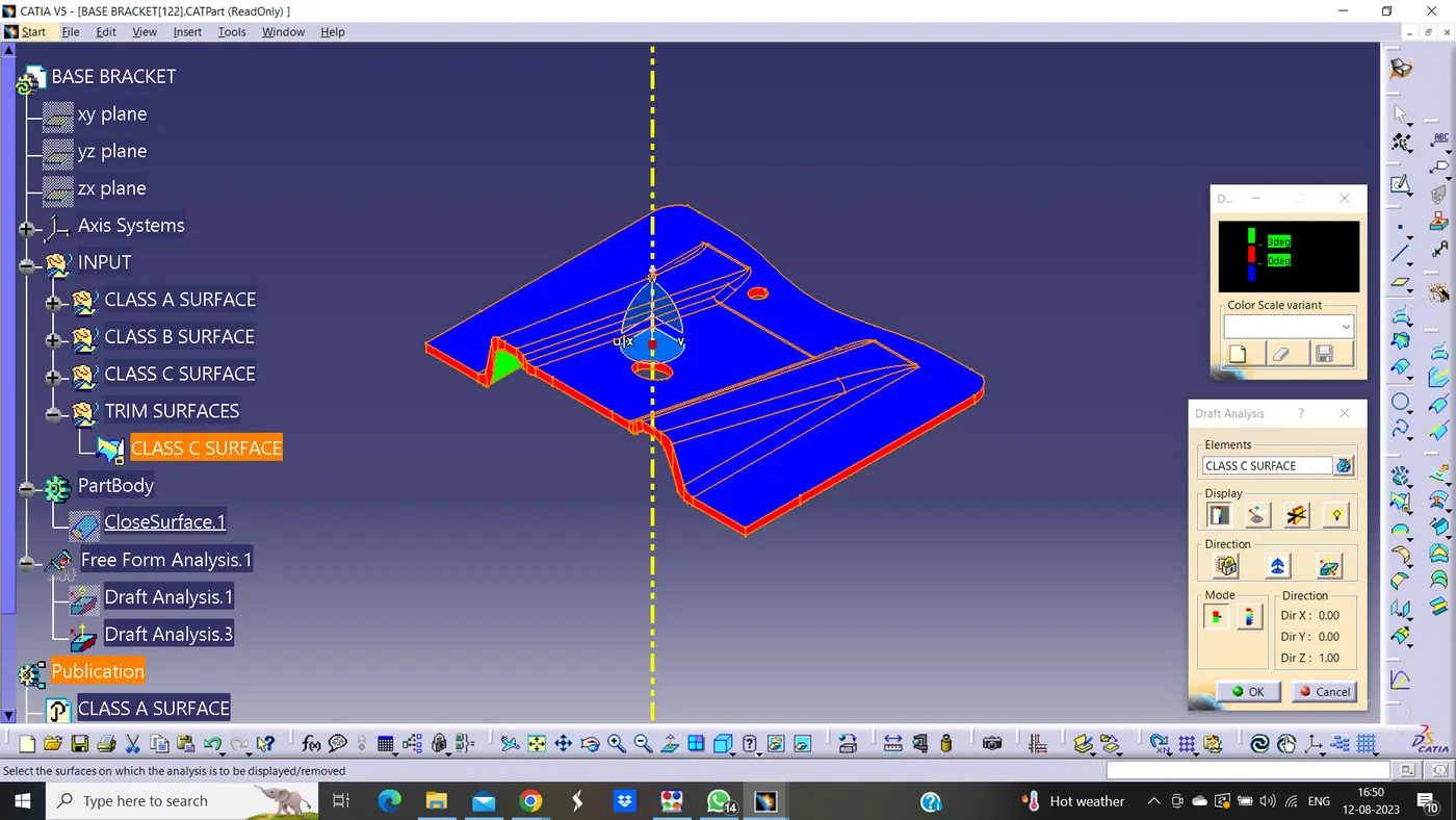
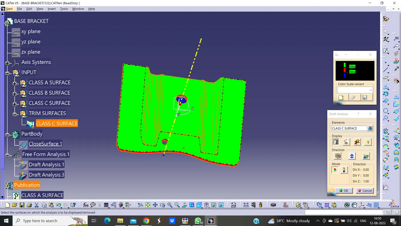
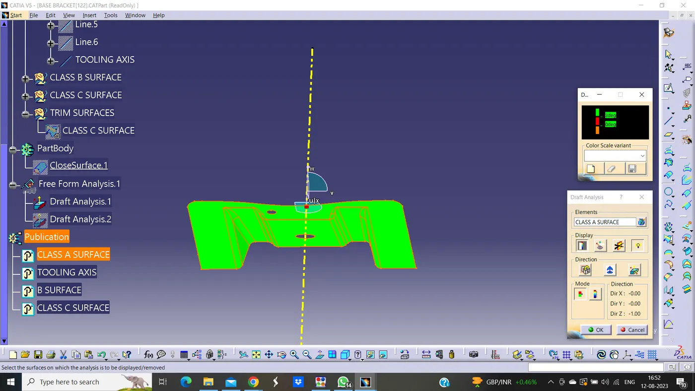
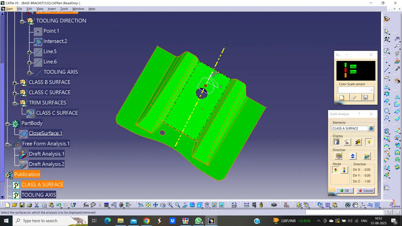
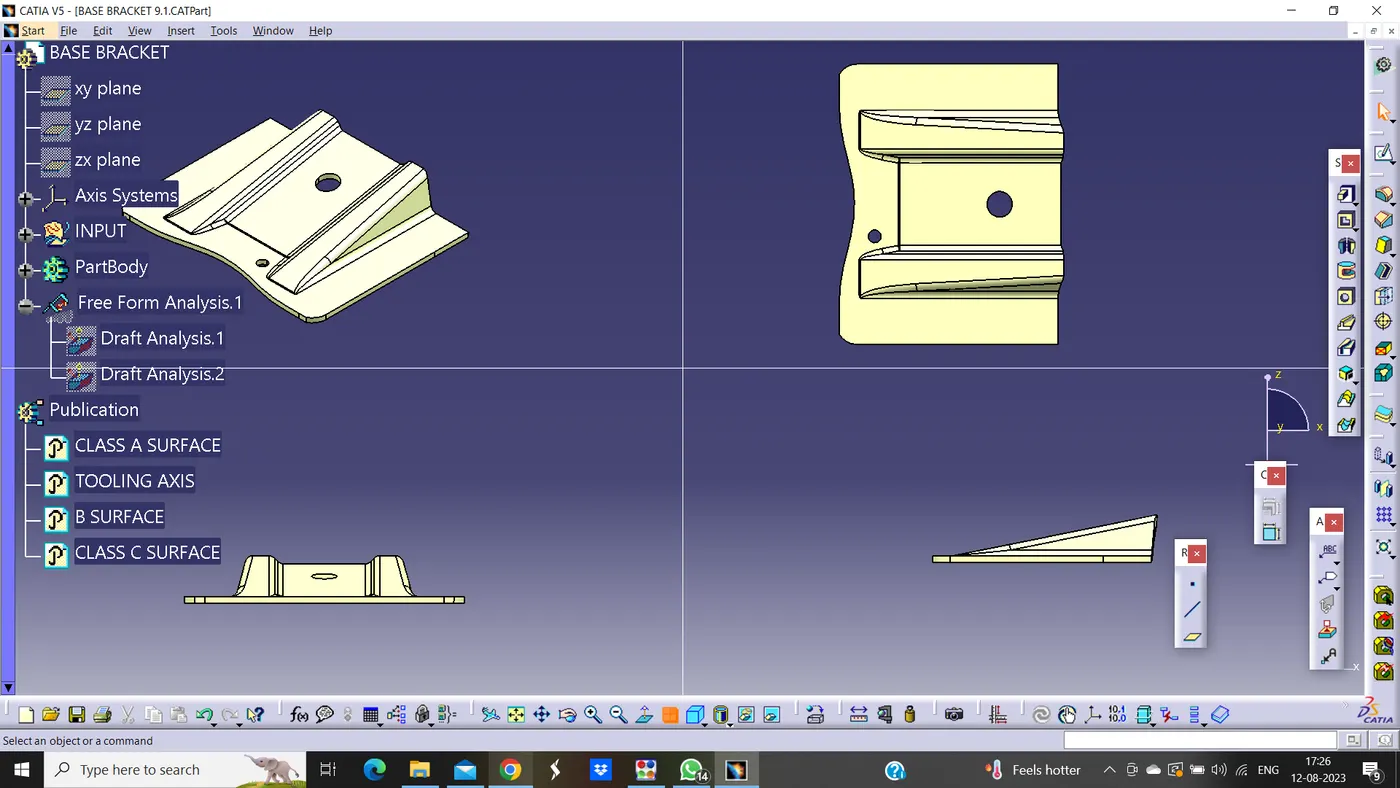
The tooling axis and class-A surface were published for further easy reference .
Now create a bisecting- line with reference of the two newly created lines and point.
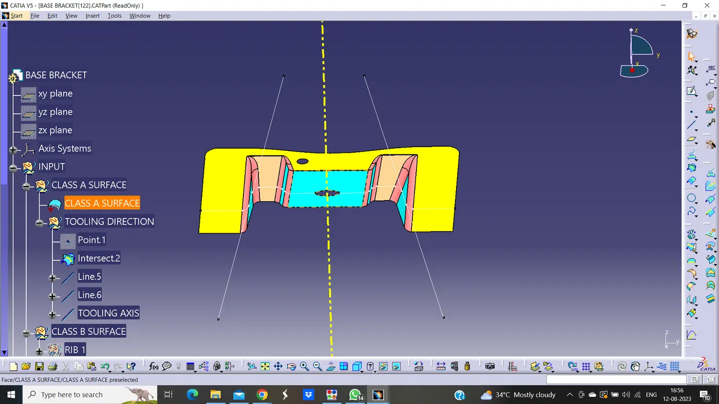
Bisecting line were used to get the exact medium so that maximum positive draft angle can be achieved.
Finally by using the bisecting line option the tooling axis were created.
Conclusion :
Thus the manufacturable Base bracket was successfully designed and analyzed draft angle using CATIA V5 Surface workbench.