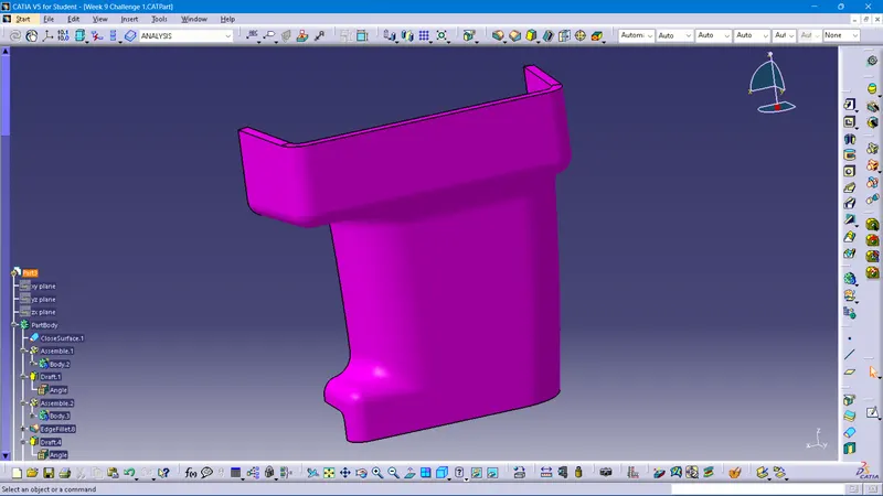
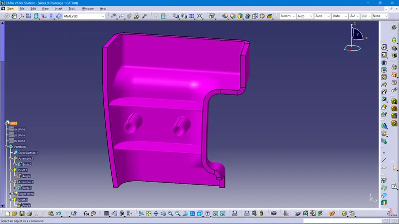
Week 9 - Attachment Feature Creation (Ribs & Screw Boss) - Challenge 1
TOOLING AXIS AND CLASS A DRAFT ANALYSIS
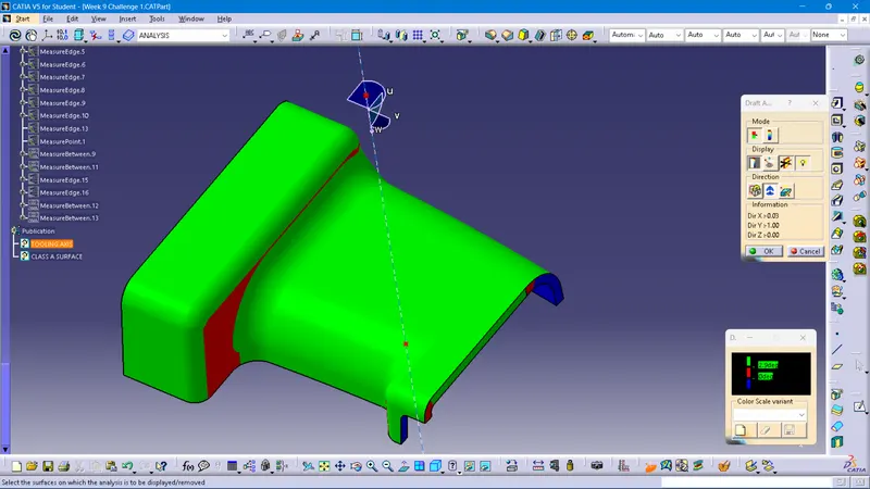
First a dummy tooling axis is created passing through the point in the plane surface, in y direction. While doing the draft analysis, some of the surfaces are below the nominal draft angle which is 3 digrees. So a plane is created in x direction, and passing through the areas where draft analysis wont satisfy. An intersect of this plane and class A surface. A line is created bisecting the lines nearly perpendicular in this intersect.
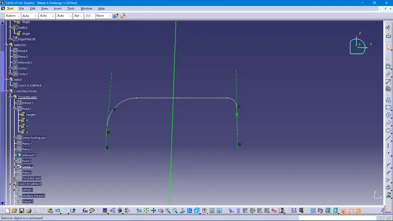
This axis is selected as the tooling axis. Still there are areas where draft analysis won't satisfy. since both inner surface won't satisfy these areas are unavidable. The draft analysis result is given below
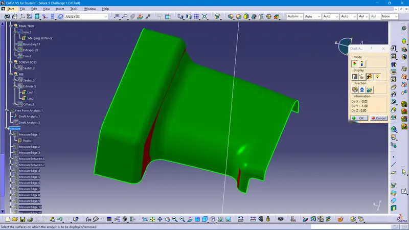
The A surface is offsetted and B surface is created by filling the missing portions. The thickness of the component is taken as 3mm. And closed body is created using this. And a draft analysis of part is conducted. Most surface are above 3 digree. But still soe of the class C surface and class A surface won't satisfy as in the Class a draft analysis. But it is unavoidable.
Class B engineering features
Class B engieering features are created following the design rules . Analysis of the rib and screw boss features are conducted. The screenshot of the analysis is given below.
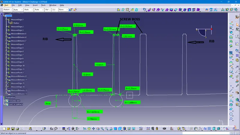
The draft analysis of the B side features are conducted. All the features satisfy draft angle greater than 0.5 digrees.
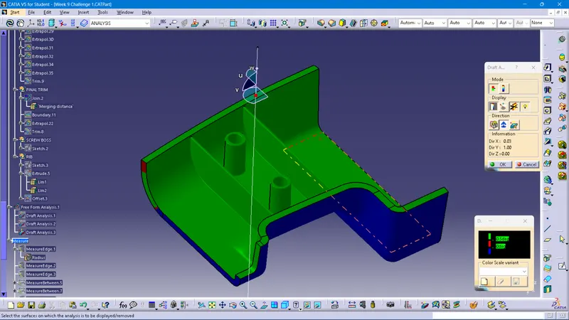
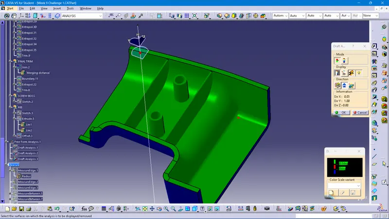
Final body