Week 9 - Attachment Feature Creation (Ribs & Screw Boss) - Challenge 1
AIM : Create the rib and Screw boss for the Drill Handle considering the design rules.
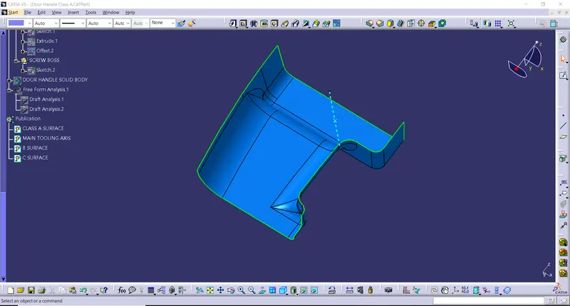
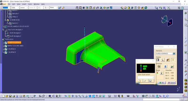
Tooling axis & Draft Analysis: The direction in which the mold or core and cavity opens is the tooling axis.
To create the tooling axis, I extracted a surface from class A and created a point in the middle of the surface by using the point command and created a line at that point through the x-axis.Now, I performed a draft analysis check from that line whether the created tooling axis is in the correct position or not. If, in the draft analysis check the surface highlighted with green colour on both sides of the surface the tooling axis is in the correct position and direction.
CLASS B SURFACE:
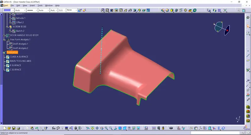
To create the class B surface, offset the class A surface inside as per given thickness ( offset the class A to 2.5mm inside). Once the offset is created, we can observe some patches on the offset surface by taking the boundary for the offset surface, those patches are formed due to the fillets on the class A surface. We need to cover those patches with the help of the multi-section surfaces command by extracting the patch boundaries. Once all the patches on the offset are covered properly join all the patches with the offset surface, to get the replicated surface of the class A surface.
CLASS C SURFACE:
To create the class C surface concerning the boundary of the class A surface, used the sweep command to do the class c surface. Initially, I extracted the boundary of the class A surface with supperatly, and I sweep the extracted boundary concerning the surface at 90deg (for reference Surface) for 5mm to intersect properly with the class B surface. Then join both class A & C surface together.
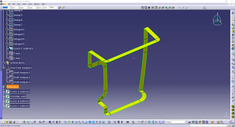
Now, join both class A and sweep boundary to get the complete class C surface.
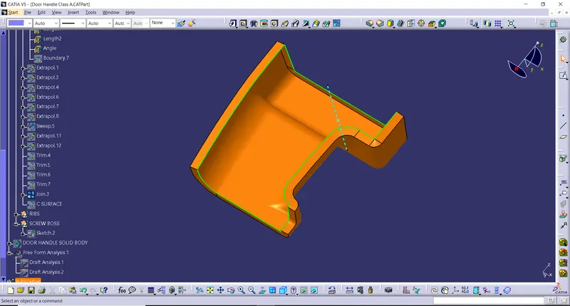
Now, take the class B and class C surfaces. Check whether all the sides of class B and Class C surfaces are intersecting properly with each other, to get a closed surface by trimming class B and class C surfaces. If the class B and class C sides are not intersected properly, we need to extrapolate the sides of the class B surface which are not intersecting with the class C surface. After check class B and class C surface boundaries whether all the sides are intersecting or not with each other. Once the surfaces are intersecting properly trim them together to get a closed surface.
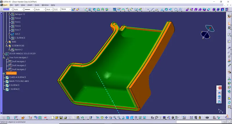
CLOSED SURFACE
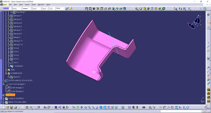
PART BODY:
To create the solid part body from the closed surface, I used the closed surface command in the part workbench.
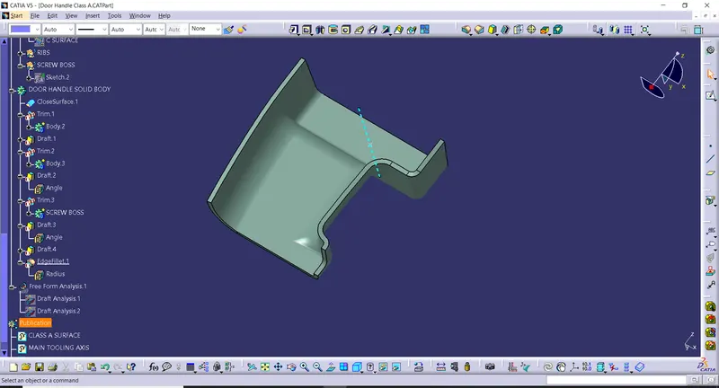
Attachment Feature Creation (Ribs & Screw Boss)
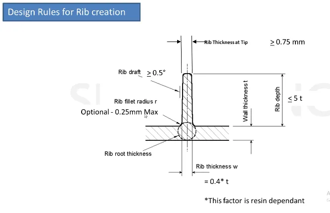
1)RIBS: - Ribs are usually designed to Improve Strength of Plastic Part without increasing the thickness of the component.
- Rib acting as stops or guides for mechanisum.
-
They are commonly used to provide additional support and strength to a part. Thickness and location are essential to rib design.
B SIDE FEATURES CREATION
RIB CREATION
Next, the profile is extruded, to find the height,h=Wall thickness * 5
h =2.5*5
h = 12.5 mm
Therefore, the height of the rib is = 12.5 mm
The extruded surface will done by using thicken commond,
Rib Thickness,w=0.4*t
w=0.4*2.5
w=1mm
Therefore, the thickness of the rib is =1mm
2)Screw Boss: -
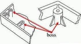
It helps to screw component together. Screws are secondary features which is on B surface. Bosses are used to attached & assembly features of many components.
SCREW BOSS DESIGN
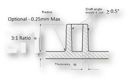
Design Principle for Screw Boss Creation
- Draft - 0.5 degrees on walls of boss
- Thickness - Typically 40%* of the nominal wall at the base.
- Height to Diameter Ratio - 3:1
- Radii - 0.25mm maximum radii.
For inner dia I taken M6 screw size Dia 5.2.
For outer hole w=0.6*t
w =0.6*2.5
w = 1.5 mm per/side
Therefore, the outer diameter of screw boss is = 1.5*2=3mm+Id 5.2= 8.2mm is OD.
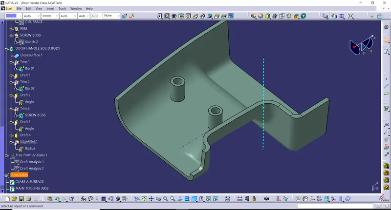
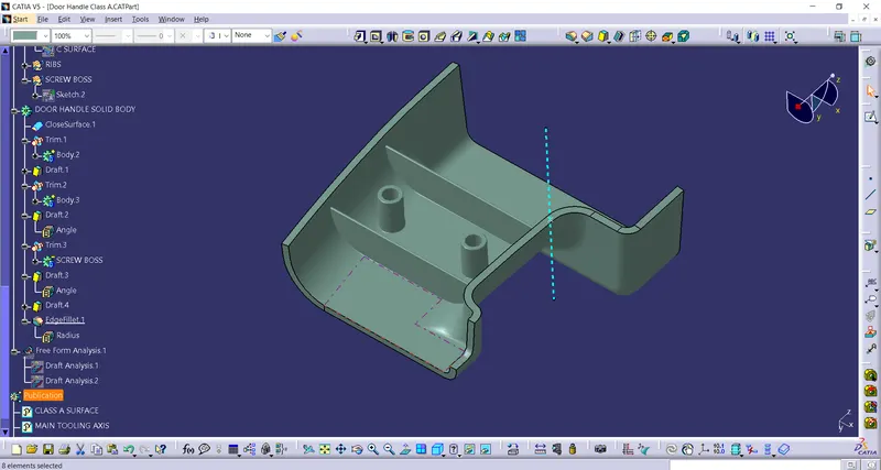
Ribs & screw boss Creactions:-
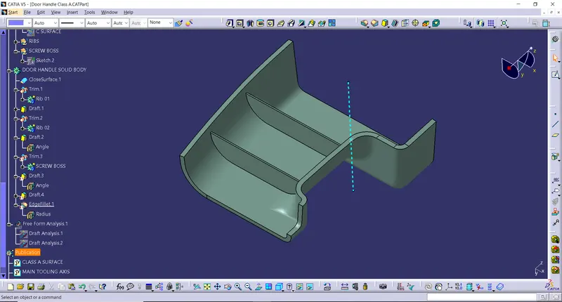
DRAFT ANALYSIS:
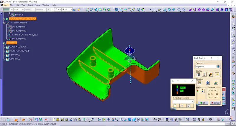
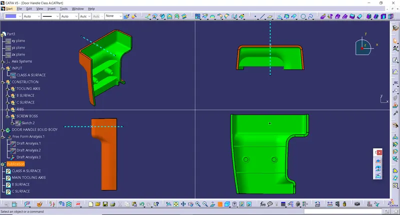
After creating a screw boss & ribs I performed a draft analysis on it, to check the draft angle(0.48 deg) of the solid body.
CONCLUSION:
Note:- Class A surface is not having a proper draft which is not clearing draft of 3deg.Due to that surface are not clearing so that class A Surface need some correction from the class a designer,for proceding for further I done with this.
PLEASE SUGGEST /COMMENT FOR ANY IMPROVEMENTS.