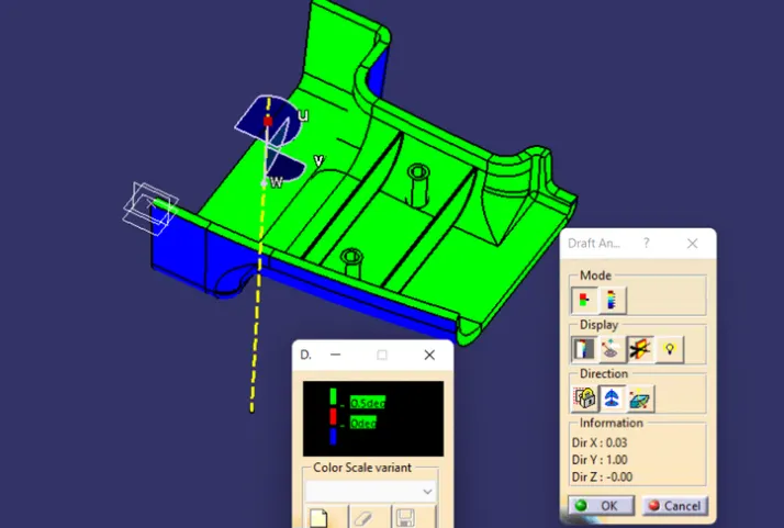
Week 9 - Attachment Feature Creation (Ribs & Screw Boss) - Challenge 1
AIM
To create the rib for the drill handle considering the design rules for rib creation and screw bosscreation and then perform the draft analysis is for the final component.
OBJECTIVE
- Create the tooling axis by using the bisecting method.
- Design the class-B and class-C surface and join them.
- Creat the solid feature by surface we create.
- Design the required ribs and screw boss and analysis them.
- Perform the draft analysis for the final component.
TOOLING AXIS
Class-A surface is first analyzed to creat the tooling axis or tooling direction that molds pull a part in injection molding. Tooling direction that molds pull apart in injection molding.Tooling direction is important for plastic product design as it decides the direction for mold separtion.
Draft Analysis :
The Draft angle is the amount of taper for molded or cast parts perpendicular to the parting line. It can be measured in degrees. A functional part for injection molding has to have Drafts facing both cavity and core sides to reduce the risk of damage to the parts and ensure ejection. And also important is to overcome the vacuum forces by letting air in between the metal to the plastic for the part to release properly. Adding maintaining a decent cosmetic finish.
Tooling axis creation :
The first step is to observe the given class-A surface deeply and we can say the larger flat area which is perpendicular to the Tooling axis. So, by considering this thing for this class-A surface tooling direction will be in the X-direction. so we create the point on the flat surface as shown in the figure.
And next is to create the reference line or axis from the Z-direction using the sketch and bisect line as shown in the figure.
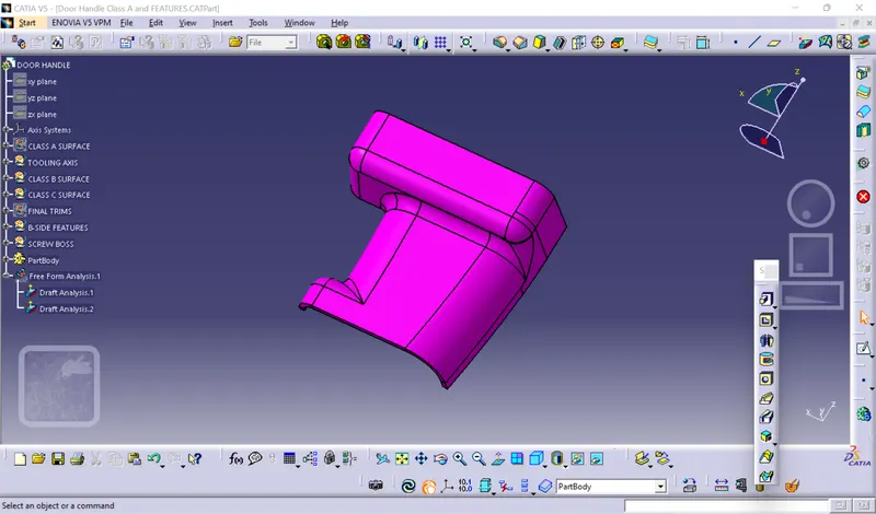
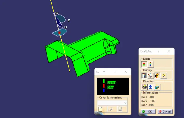
Draft Analysis :
- The part created has to be changed to modes in the display frame.
- Compass is enabled aligned light along with the tooling direction.
- Lock command is then applied to fix compass along with tooling axis.
- Color codes are classified and Draft angle is applied.
- Running point analysis is used to display permissible draft and angles
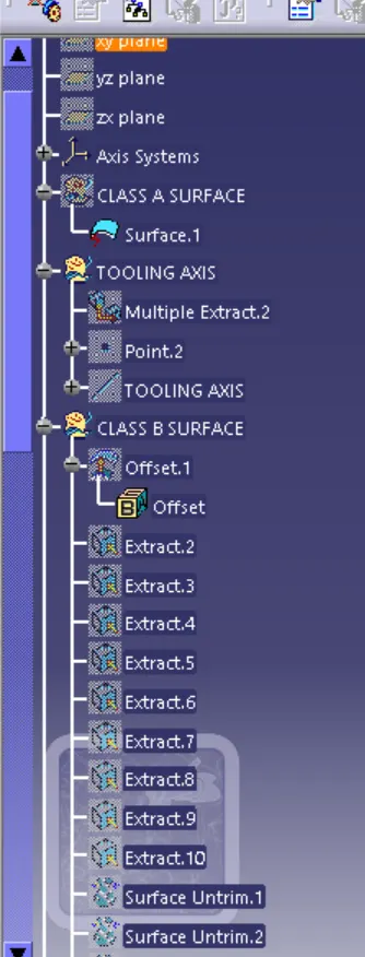
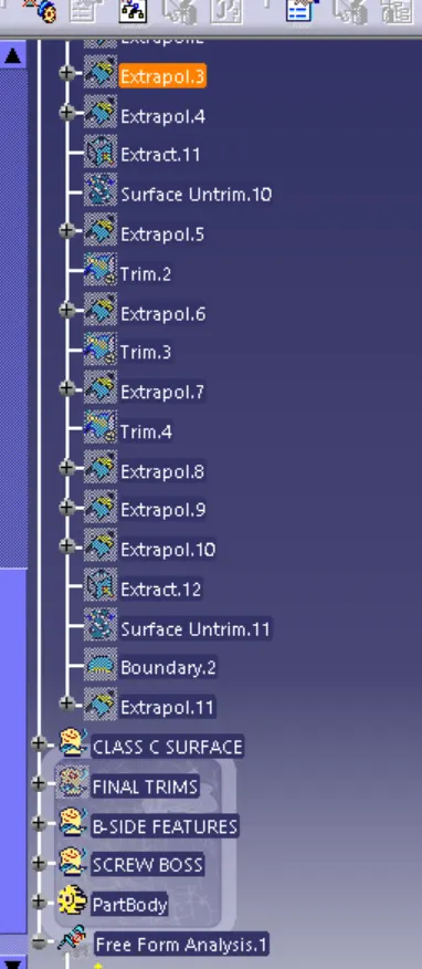
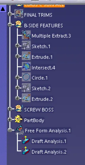
Tree structure
Analysis for Ribs Dimension
The analysis for the dimension is one of the very important analyses to avoid problems in the injection molding process for the component dimensions. the problems like sink marks, flow lines, weld lines, and warping. Then they create some for creating the ribs. That standard dimension is shown in the figure.
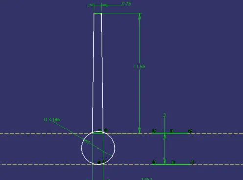
CLACUTION FOR RIB
|
Analysis for Screw boss Dimension
The analysis for the dimension is one of the very important analyses to avoid problems in the injection molding process for the component dimensions. the problems like sink marks, flow lines, weld lines, and warping. Then they create somesamendard for creating the ribs. That standard dimension for creating a Screw boss is as shown in the n figure.
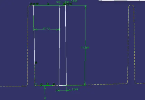
CALCULATION FOR SCREW BOSS
| S NO | AREA | SPECIFICATION | OBSERVATION | STATU |
| 1 | Heigh(H) | 5t 15mm Max | 11.36mm | OK |
| 2 | Thickness | 0.4t 1.20mm Max | 1.05mm | OK |
| 3 | Thick at Top | >0.75 0.75mmMin | 0.79mm | OK |
| 4 | Diameter(D) | H=3D 3.78mm Max | 3.71mm | OK |
| 5 | Fillet radius | >0.25 0.25mm Min | 0.25mm | OK |
| 6 | Draft angle | >0.5 0.5Deg MIN | 0.60 Deg | Ok |
Analysisnlysis
- The part created has to be changed to the modes in the display frame.
- Compass is enabled and aligned along with the tooling direction.
- Lock command is then applied to fix compass along with tooling axis.
- Color codes are classified and Draft angle is applied.
- Running point analysis is used to display permissible draft angles