Week 9 - Attachment Feature Creation (Ribs & Screw Boss) - Challenge 1
AIM
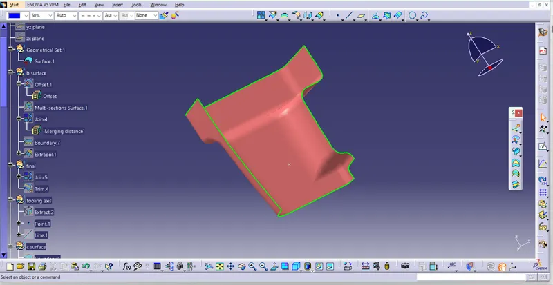
Create the component through the given Class-A surface.
the tooling axis for the given Class-A Surface should be created meeting the requirements of the draft angle and at the end perform the Draft analysis on the model. Create the rib and screw boss as by considering the design rules
CLASS A SURFACE
DRAFT ANALYSIS
- Draft allows for the component to release from the mould, most parts or applications require a minimum of 0.5 to 1 degree draft angle and 3 dgree draft angle is widely used as per the norm.
- Change the material mode to customize mode before moving to the draft analysis.
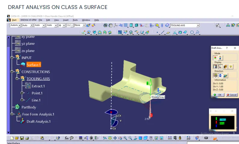
- Insert –analysis-feature draft analysis
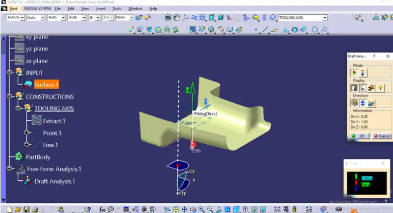
- Defining the draft direction Select draft analysis from the tool bar and click on the compass symbol and pull the compass from the right side top corner of the workbench and place it on the component where want to do the draft analysis. ‘W’ of the compass and tooling axis should be aligned on the same line.
- Once the compass is aligned with the tooling axis click on the lock symbol and drag on the surface we will get a wrong mark then select that point a table will appear it shows the draft value on the table we can adjust the draft value and analysis it for all the edges and surfaces.
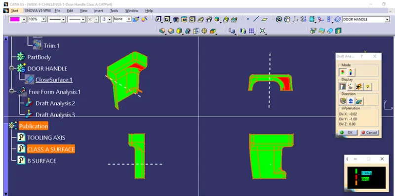
- By clicking the on the surface and using the flipping tool we can assign the Flipping direction, the color of the surface change as per the flipping direction .
- Analysis under running point and move the mouse on the surface and it will show the details of the surface deg direct at each and every point of the surface.
CREATION OF TOOLING AXIS
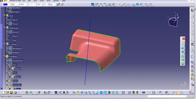
TOOLING AXIS is created by bisecting the axis created on two intersections .
The best tooling direction for the class-A surface is along y-axis direction.
Flat surface on the center part is extracted for creating the tooling axis in y direction
Then created a with the point and direction along y axis.
CLASS B CREATION
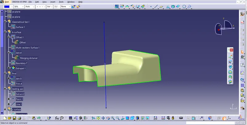
- Take a 2.5mm Offset from Class A Surface upward towards the unfinished surface we get .
- Take a multi section surface to fill it and join the both surfaces, This is Class B Surface.
C SURFACE CREATION
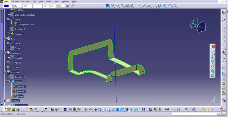
- Unhide the A Surface to Take a boundary as a reference to make C surface.
- Go to sweep line-> with Reference Surface 87 degree draft angle for all sweep.
- And join all the sweep parts to make a Class C surface.
FINAL TRIM
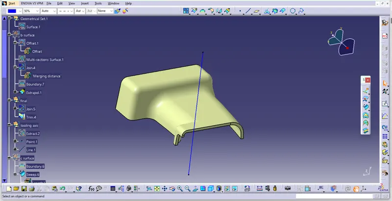
- Take a Joined part C Surface And A Surface to Trim with Class B Surface, we get the output closed surface body.
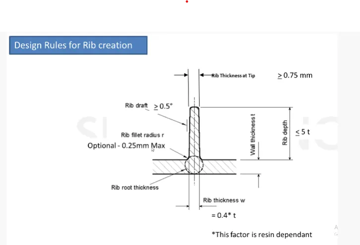
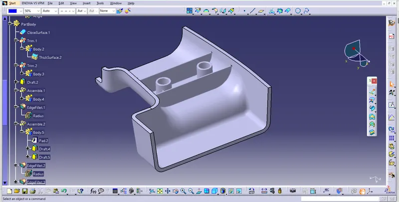
RIB CREATION
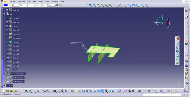
- Create a plane on the surface where we need and make a sketch 2 parallel lines,
the values I used mentioned the diagram given below.
SCREW BOSS CREATION
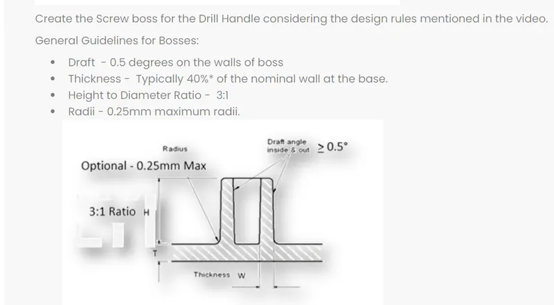
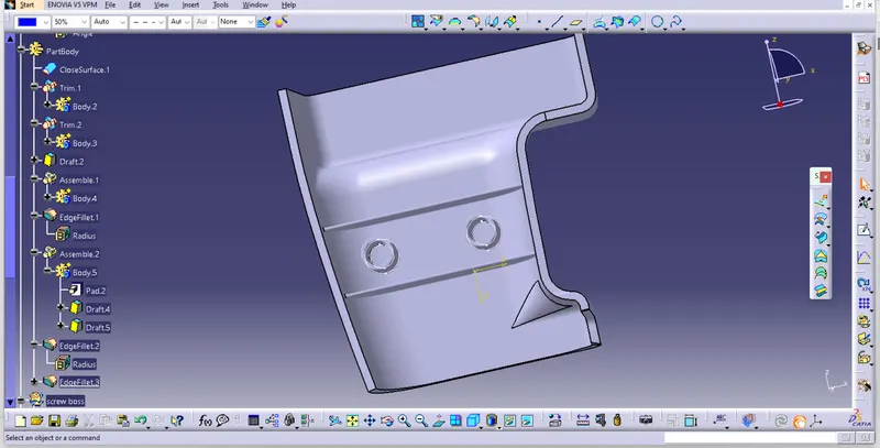
- Using a plane create for ‘Rib’, create a sketch, the measurements are taken by diagram given below.
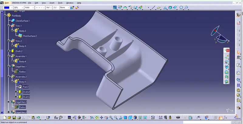
TREE STRUCTURE
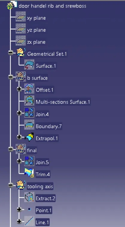
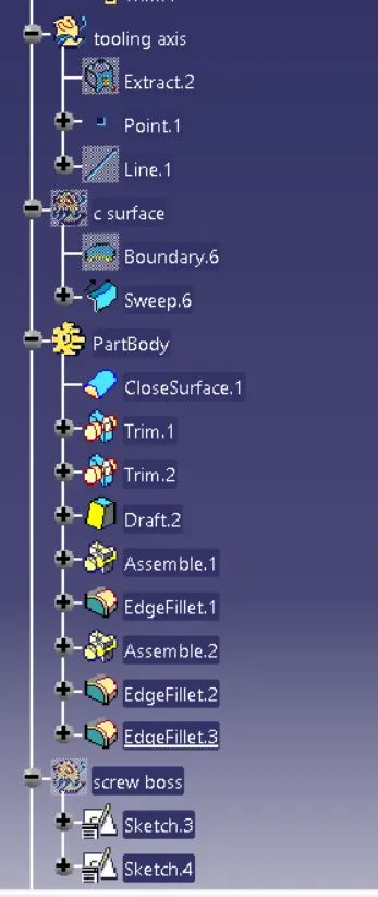
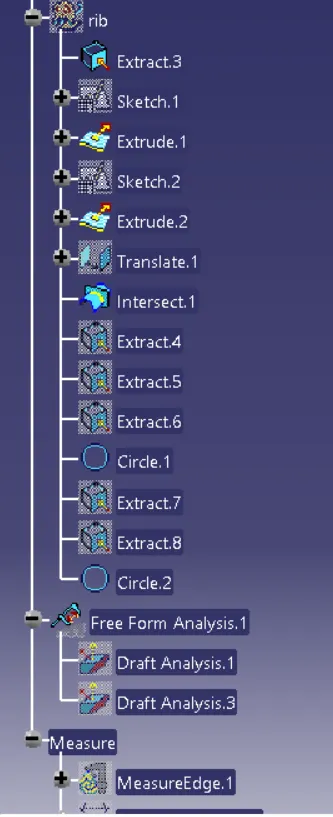
CLOSE SURFACE
CONCULTION
The report of “DOOR Handle” with Attachment feature Creation (Ribs & Screw Boss)