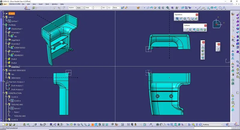
Week 9 - Attachment Feature Creation (Ribs & Screw Boss) - Challenge 1
REPORT:
AIM:
To create class tooling axis, B, C & the rib, and screw boss considering the design rules.
PROCEDURE:
1. Tooling axis: First I extract the bottom surface of class A and created a point. Then I define a line by the type of point to direction through Y direction.
2. Class B: Extract and untrim and extrapolate each class A surface, and trim the surfaces to join. Then offset the surfaces to the given thickness of 3 mm.
3. Class C: created a boundary layer for class A. sweep the boundary layer as a guide curve and class A as the reference surface.
4. Final: Finally trim the Class A, B, and C. And checked it is a closed surface. Publishing the class A, class B, class C, and tooling axis.
5. Solid part: Next convert into a solid part through the closure surface option in part design.
6. Draft analysis: Then Insert draft analysis, pick the compass, placed it in the tooling axis, and used the compass to define the new current draft direction., then locks the draft direction. then the green color surface denotes that the surface is up to 3 degrees.
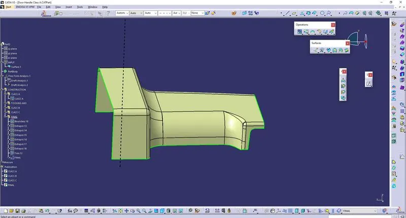
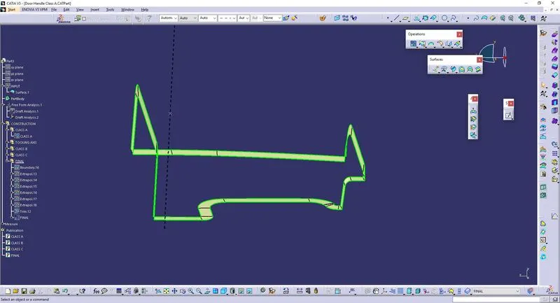
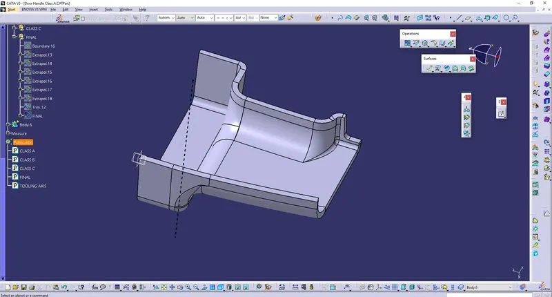
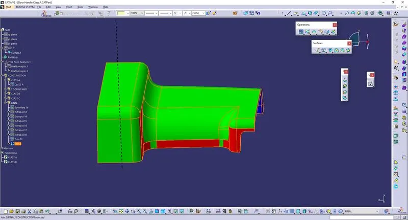
Here the given class A styling surface having some issues.
RIBS: To create the rib for the Drill Handle considering the design rules
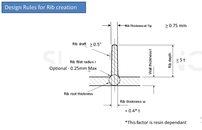
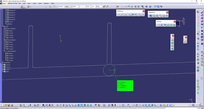
SCREW BOSS: To create the Screw boss for the Drill Handle considering the design rules.
DESIGN RULES FOR SCREW BOSS:
- Draft - 0.5 degrees on the walls of boss
- Thickness - Typically 40%* of the nominal wall at the base.
- Height to Diameter Ratio - 3:1
- Radii - 0.25mm maximum radii.
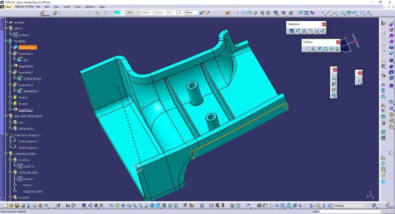
FINAL RESULT: