Week 9 - Attachment Feature Creation (Ribs & Screw Boss) - Challenge 1
RIBS & SCREW BOSS
AIM:
- To Create the Door Handle Component from the given Class-A surface.
- To Create the tooling axis for the given Class-A Surface meeting the requirements of the draft angle.
- To Attach B side Features in the component.
- To perform the Draft analysis on the model.
TOOLS USED:
- Boundary
- Join
- Multiple extract
- Bisecting line
- Trim
- Surface offset
- Draft analysis
- Intersect
- Surface sweep
- Close body surface
DESCRIPTION:
1. CREATING TOOLING AXIS -
The Tooling Direction is basically the direction that the mold pulls a part. The mold is built in two separate pieces, basically. You have a Cavity side and you have the Core side. The Core pulls apart from the Cavity and that's the Dye line or the Tooling Direction.
- Open the given CAT part file.
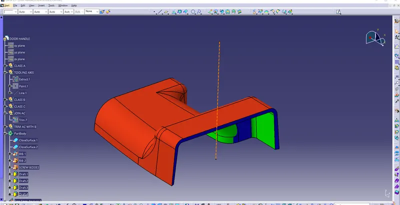
DRAFT ANALYSIS
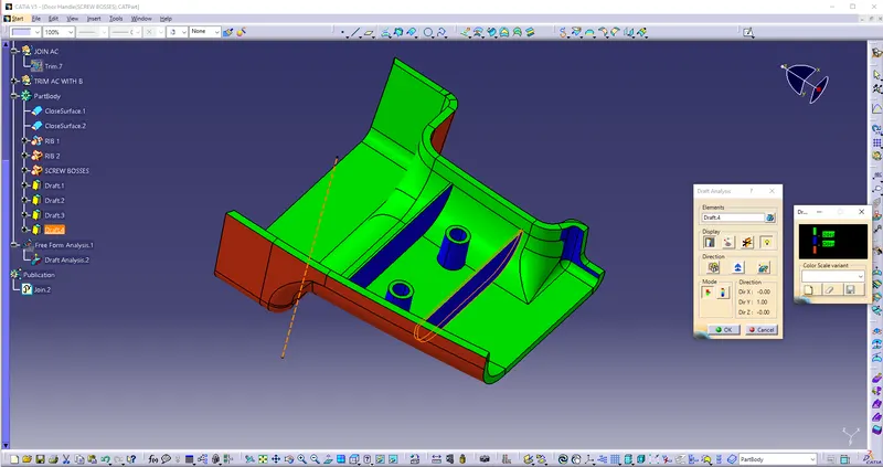
Draft analysis is a method used in design to check whether the component created in CAD is manufacturable based on the draft condition applied. The main reason behind the draft analysis is the part manufactured should be easily removed from the mold. It also gives an idea of the draft angle from the tooling direction. Here we are giving a tooling direction in order to eject the component easily from the tool. The ideal draft angle given in automotive industries for plastic components is 3 degrees.
Some of the components where draft analysis is done are hood, fenders, roof, side doors, etc.
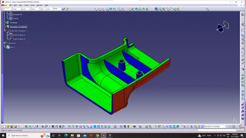
The draft analysis is an important tool as it helps the user to analyze the draft on various surfaces, the draft analysis in CATIA uses the color codes for the identification of the draft. Each color has its own meaning for the minimum draft negative draft and under draft.
The draft analysis toolbar provides two modes for analysis of the draft, first is the quick analysis which basically has three colors for analyzing GREEN, RED, AND BLUE on the other hand other option is the full analysis mode which enables a few more details into the draft and is used in the complex components like the instrument panel, etc. In the above challenge, we have used the quick analysis made for analyzing the draft here. Now, bring the compass and align it with the tooling axis and click the lock button in the dialog box.
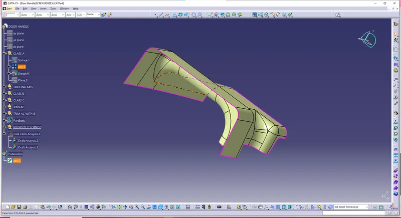
.CLASS A SURFACE : Asurface is the aesthetic surface created by the class-A engineer. It is the visible aesthetic surface of any automotive component. class A surface is any of a set of freeform surfaces of high efficiency and quality.
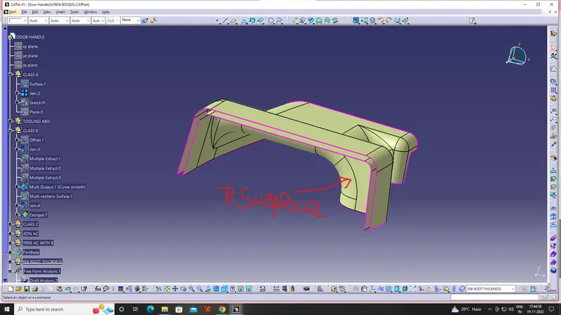
CLASS B SURFACE : B surface is the offset of the class A surface. Class B surfaces are Engineering Surfaces which are invisible to the eyes or often on the back side of the Class A surfaces. It is mainly the thickness of the component or Class A.
CLASS C SURFACE : C surface is joining surface between A and C. Class C surfaces are connectors between Class A and B surfaces. This surface connects both A and B surfaces along the Tooling Axis. It contains the draft as per the design. Its is basically the thickened surface between both A and B surface.
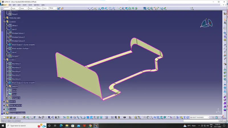
JOIN A & C SURFACE :
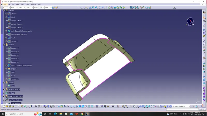
TRIM AC WITH B SURFACES:
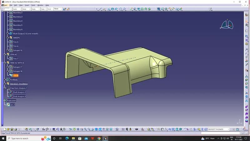
PART BODY:
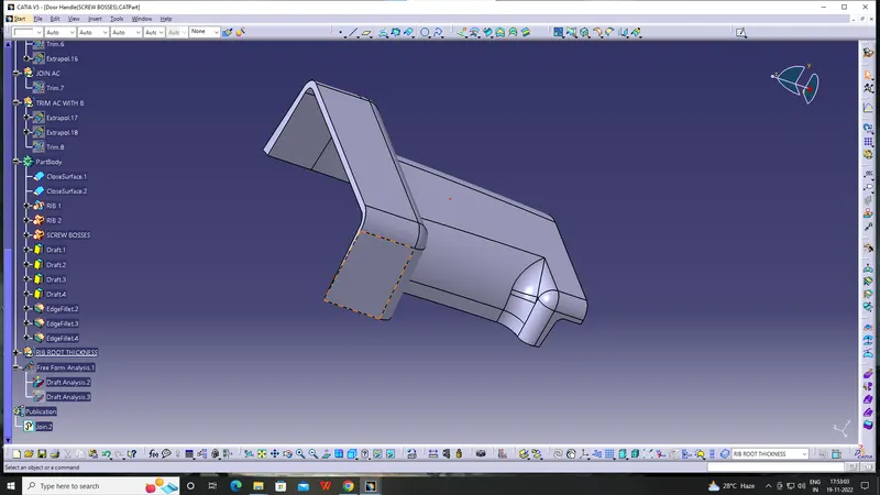
Ribs & Screw Boss :
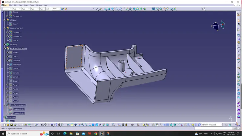
RIB CREATION
- Design Principle for Rib Creation
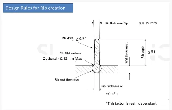
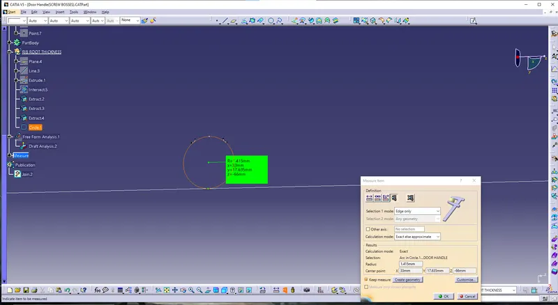
General Guidelines for Bosses:
- Draft - 0.5 degrees on the walls of boss
- Thickness - Typically 40%* of the nominal wall at the base.
- Height to Diameter Ratio - 3:1
- Radii - 0.25mm maximum radii.
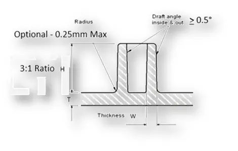
Screw Boss:
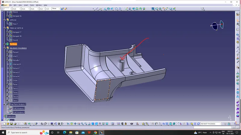
FINAL DRAFT ANALYSIS:
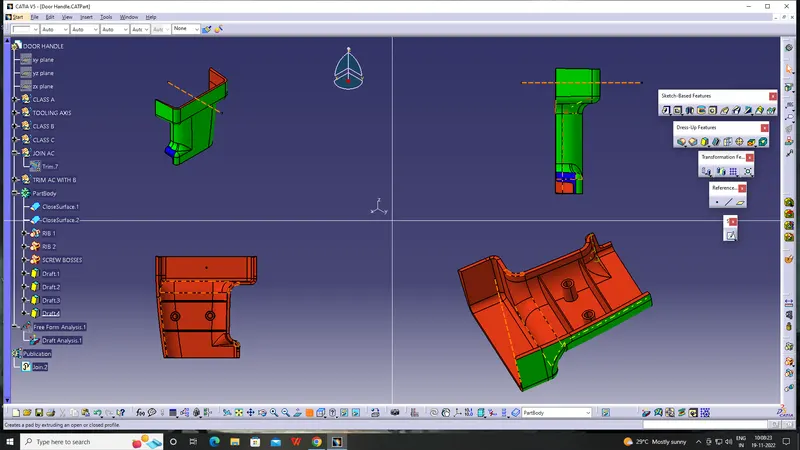
MULTI VIEW:
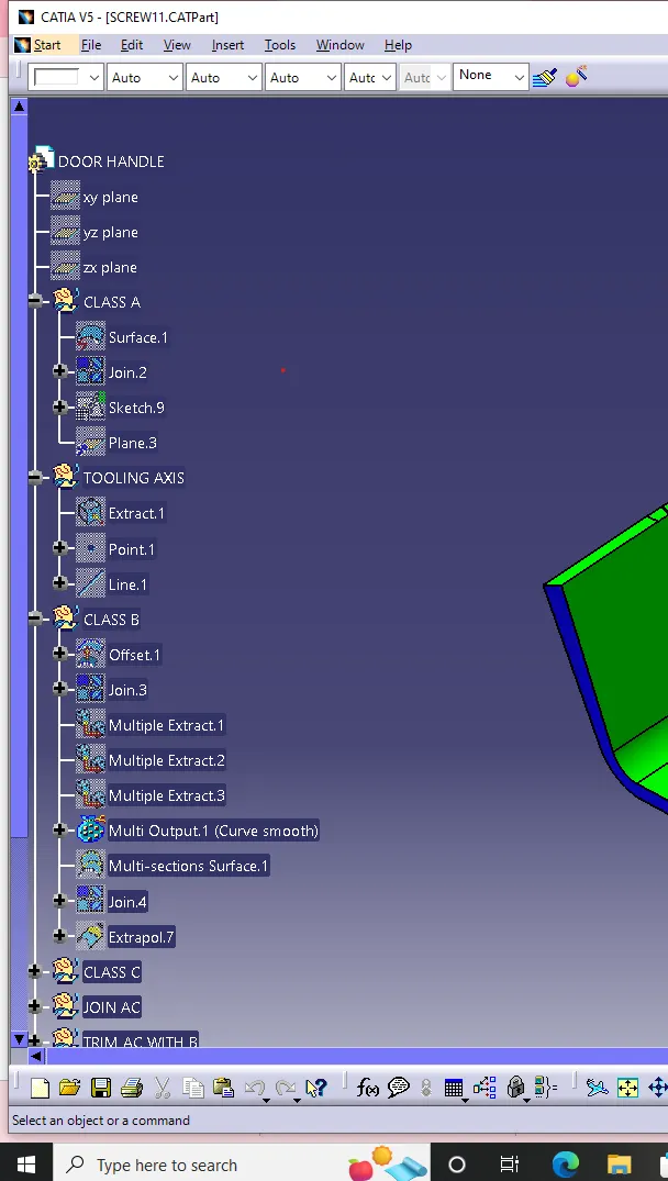
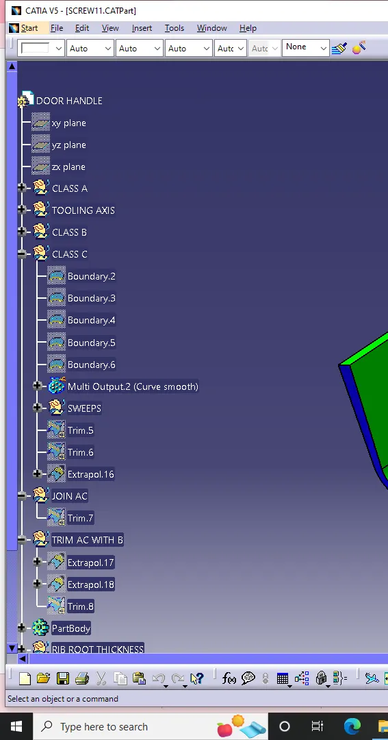
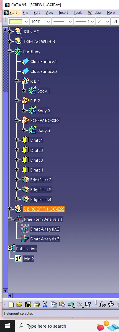
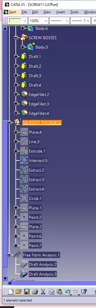
FAMILY TREE:
RESULT:
Ribs & Screw Boss plastic component using class-A surface successfully created and performed the draft analysis on the class-A surface and final plastic component.