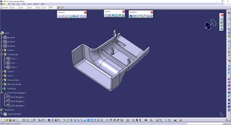
Week 9 - Attachment Feature Creation (Ribs & Screw Boss) - Challenge 1
Class A Surface:-
# its the surface which will be visible to the coustomer
# it contains all the asthetic shape and high surface quality
# its the surface which is used to creat plastic part
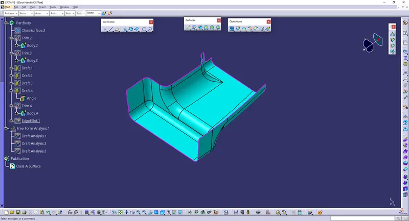
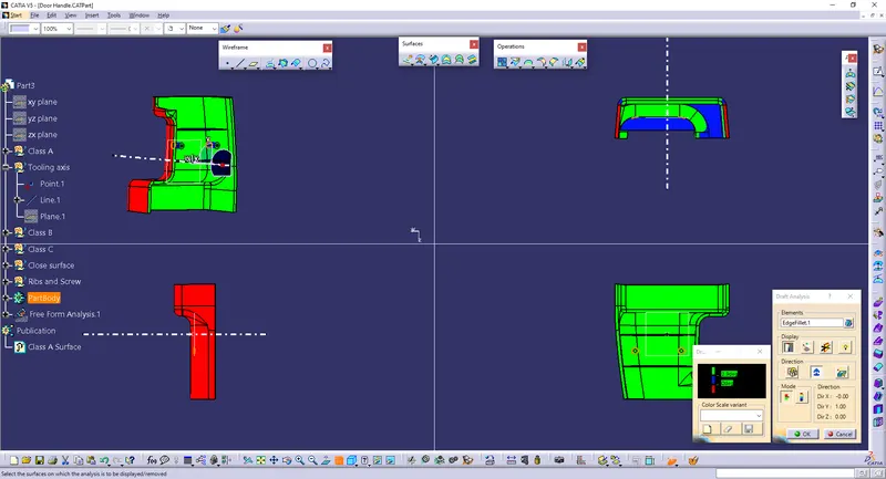
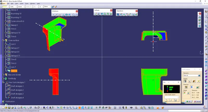
Draft Analysis:-
# The draft analysis technique is used to analyze whether our part model created in CAD is manufacturable based on the draft condition applied
# Green denotes the draft angle is standard 3 degree
# Blue denotes it is below 3 degree
# Red denote that the product is not productable
In this design I have used 90deg draft angle
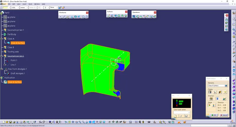
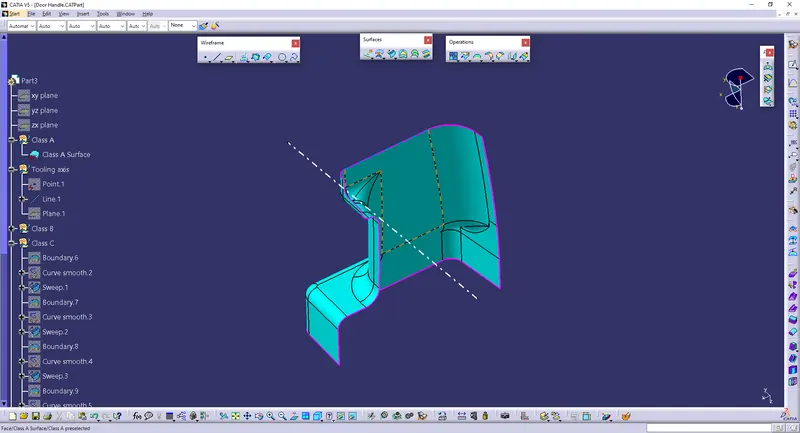
Tooling Axis:-
# The direction in which the mold called the tooling axisor core and cavity opens is tooling asix
# The drafting angle (3 degree) will be considered according to the tooling asis
# The white which passes through the class A surface is called tooling axis
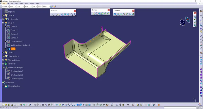
Class B Surface:-
# it is the inner surface of the model which will not be seen by the coustomer
# it contains the engineerg aspects of the model
# it is surface where ejector pins will make contact
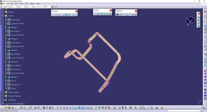
Class C Surface:-
# It is the surface which joins Class A and Class B Surface
# It determines the thickness of the model
# it is not visible most of the time
Rib & Screw Bosses:-
Considering the rules for designing the RIB dimension taken:-
T=0.5 object thickness
A=0.4 * T= 0.4 * 2.5=1 Rib thickness
B=4*T=4*2.5 =10 Rib height
E= 2 deg Draft
Considering the rules for designing the Bosses dimension taken:-
Considerig the screw to be M5
D=5 Outer diameter
d=2.5 Inner diameter
B=10 Height
E=2 Draft