Week 9 - Attachment Feature Creation (Ribs & Screw Boss) - Challenge 1
Week 9 - Attachment Feature Creation (Ribs & Screw Boss) - Challenge 1
OBJECTIVE
- To create and Develop Class B and Class C surfaces along with proper Tooling axis from the Given Class A surface
- To create and Assemble of Ribs and Screw Boss to the complete part body of Door Handle.
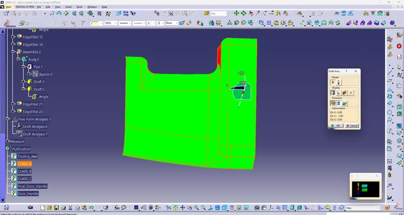
- Draft analyse the both class A and completed part body of door handle.
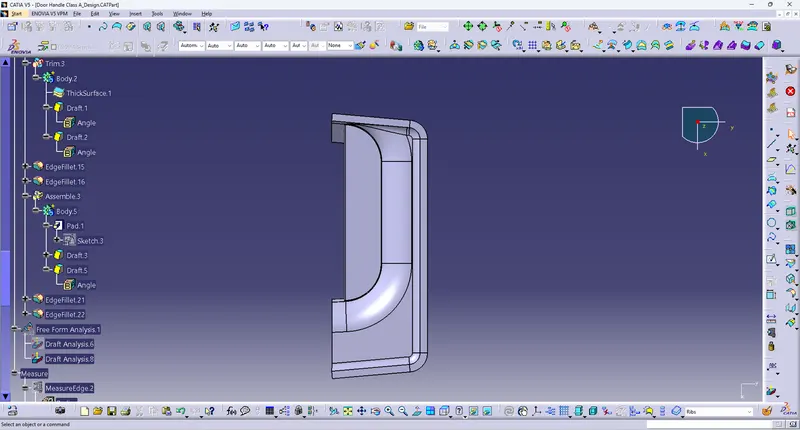
Screenshot of Class surface of Door Handle
Tooling Axis
- To Extract the bottom/Flat surface and create a point on the surface
- then add axis system, on the reference point and intersect along the YZ axis
- In the intersection lines ,create two lines and Create bisecting line from these two lines
- And consider as Tooling Axis
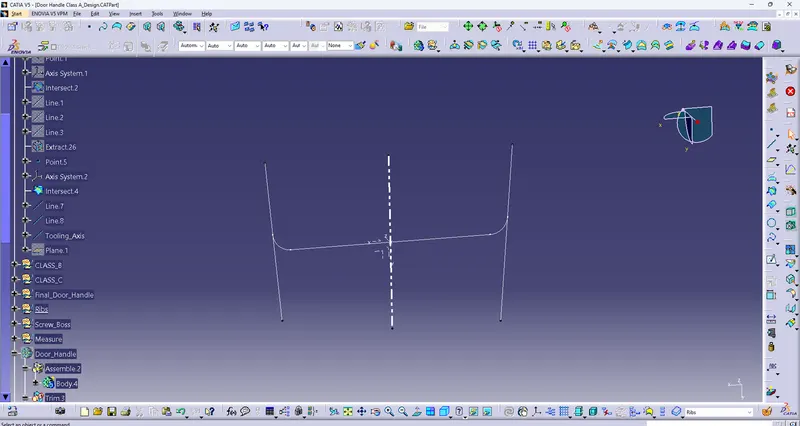
Screenshot of Tooling Axis
Draft Analysis of Class A Surface
Class B Creation
- Extract all the face of surface from the Class A surface Except Fillets
- Then Extracted surfaces all untrim and Extrapolate the surface wheather intersect to other surface
- Afterthat Trim all the surfaces and offset to 2.5mm distance to inward direction,Because component thickness is 2.5mm
- then fillet all edges with measure of class A surface and also consider thickness of component
- If fillet is inward minus the thickness value to the fillet value get from class A surface
- If fillet is outward adding the thickness to the fillet value
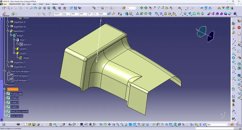
Screenshot of Class B surface
Class C creation
- From the Class A surface, selects boundary and sweep
- In sweep,With reference surface select boundary as a guided curve and ref.surface is Class A surface at 90 degree with distance of 5mm
- then some curving edges are inproper surface, so resolve those surface by using Multisolid surface command
- then extrapolate corner edges were not intersect to eachother and trim the excess edges
- After Using Join command join all the sweep surfaces is consider as a Class C surface
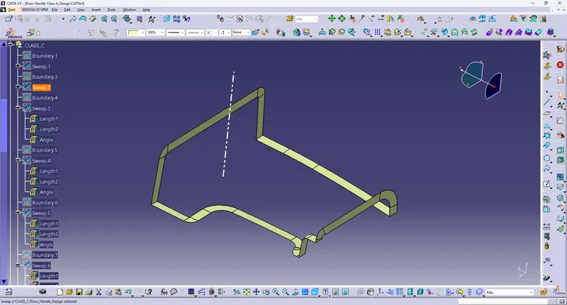
Screenshot of Class C surface
Final Component Creation
- Join the Class C surface to the Class A Surface
- And Trim Class B surface to the Join Of class c and A surfaces
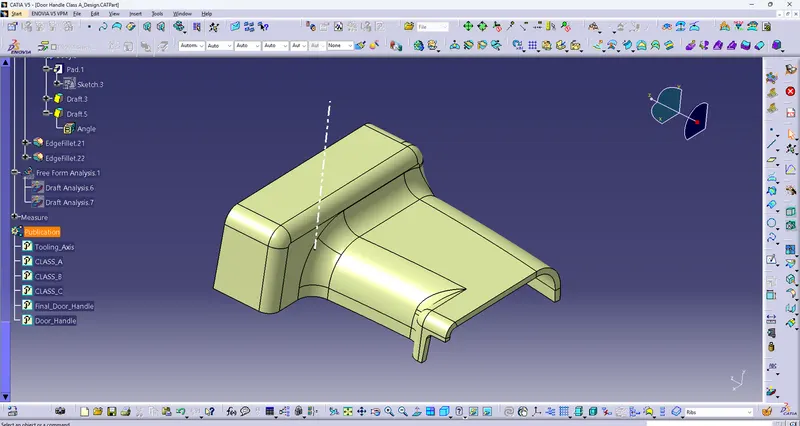
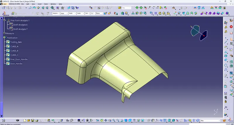
Screenshot of Final Door handle surface
- Change to Part body By using Closing Surface and Door handle solid component is completed
Ribs Creation
- Create Positioned sketch on the surface and draw a two lines and iso constraint
- Extrude those Lines at 5t Of thickness of the component at 5*2.5 is 12.5mm
- Then thicken 0.4t of thickness of the component, 0.4*2.5 is 1mm of ribs thickness
- Draft angle is 0.5 degree at pulling direction of Tooling axis and neutral element is base of the ribs
- then Edge fillet is 0.25mm
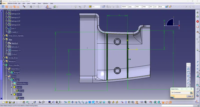
Screw Boss Creation
- Create positioned sketch of same surface and draw circle of self threading of M6 screw dia is 5.2mm
- And outer screw boss is
For thickness, the design rule is as follows,
Thickness,w=0.6*T
=0.6*2.5
=1.5 mm
Therefore, the thickness of the boss can be 1.5 mm per side.
In this case, we have considered the size of the screw boss as M06.
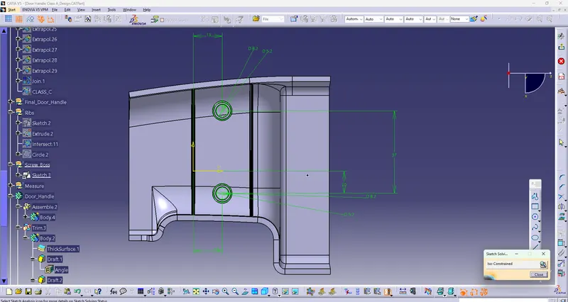
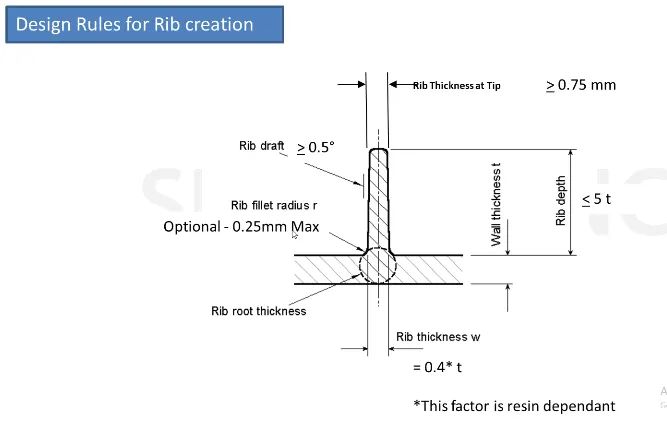
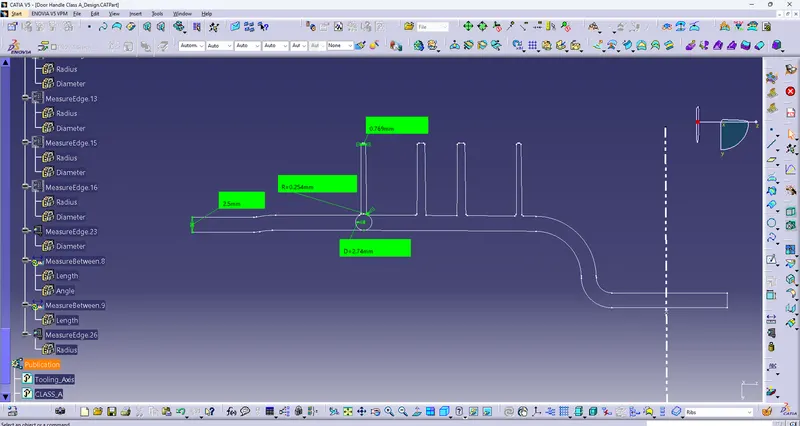
Screenshot of Rib root thickness
Draft Analysis of Door Handle Design
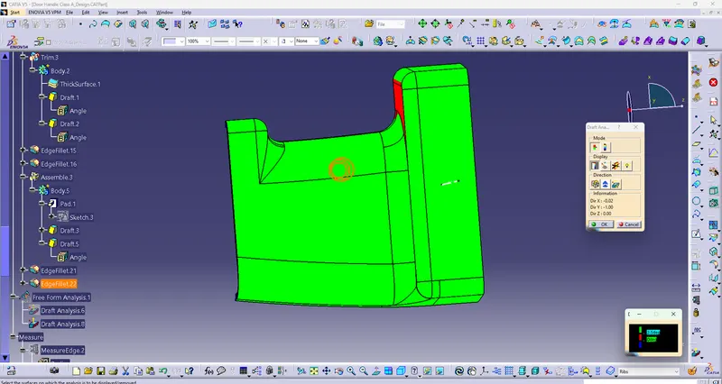
Isometric View
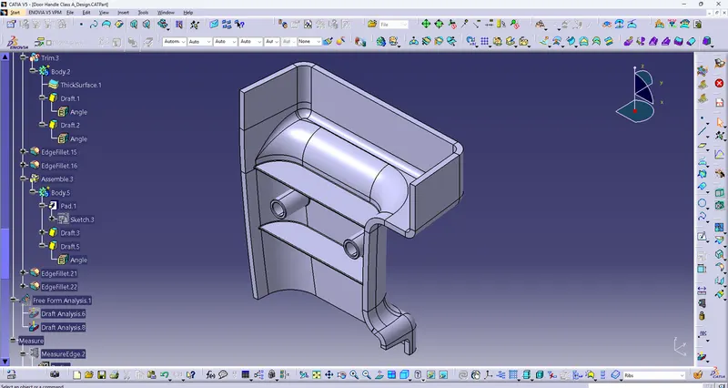
Front View
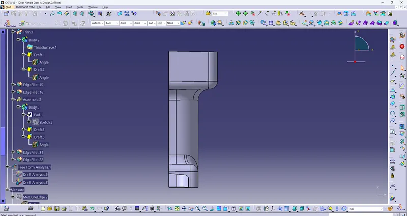
Side View
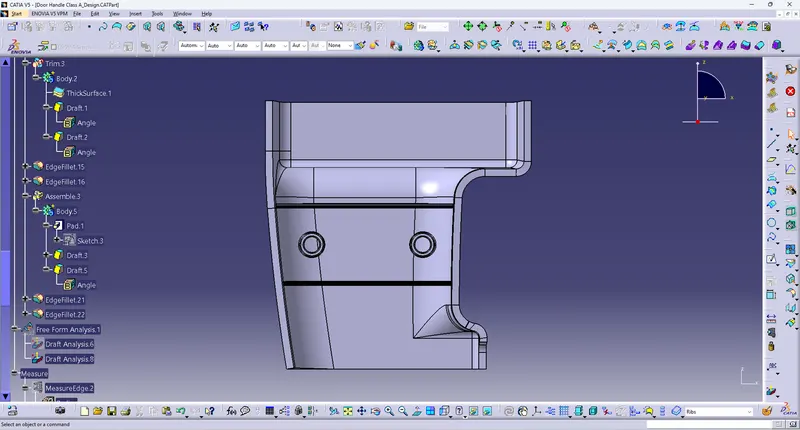
Top View