Week 9 - Attachment Feature Creation (Ribs & Screw Boss) - Challenge 1
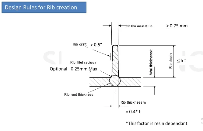
Create the rib for the Drill Handle considering the design rules mentioned in the video.
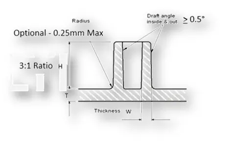
Create the Screw boss for the Drill Handle considering the design rules mentioned in the video.
General Guidelines for Bosses:
- Draft - 0.5 degrees on the walls of boss
- Thickness - Typically 40%* of the nominal wall at the base.
- Height to Diameter Ratio - 3:1
- Radii - 0.25mm maximum radii.
NOTE:
- Sketches
- Use Positioned sketch
- Sketches should be Iso-Constrained
- Tree Structure
- Ensure Proper Tree Structure
- Geometrical sets should have a proper name based on the sketches present inside of it
- All the sketches should be created under the Geometrical set
- Report
- A detailed report should be done explaining the draft analysis and the tooling axis creation.
- An explanation should be given on the way of creating the tooling axis, particularly the Bisecting method.
- Reference
- Refer to the below-given image to understand the position of the Screw Boss and Ribs
we have to create the solid part for the given class-a surface by using and class-b,class-c,tooling axis and next we have to create the ribs and screw boss
first we start from the given class-a surface
class-a surface
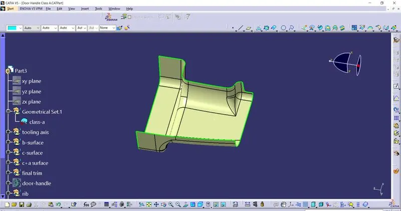
his is the class-a surface given, now we have to create the tooling axis using this
now we have find the flat surface to create the tooling axis.
for creating the tooling axis we have take the bottom face and create the point on the surface on middle and create the line perpendicular to the face and that line is called tollng axis.
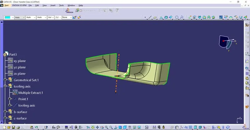
after the tooling axis we have perform the draft analysis W.R.T to the tooling axis
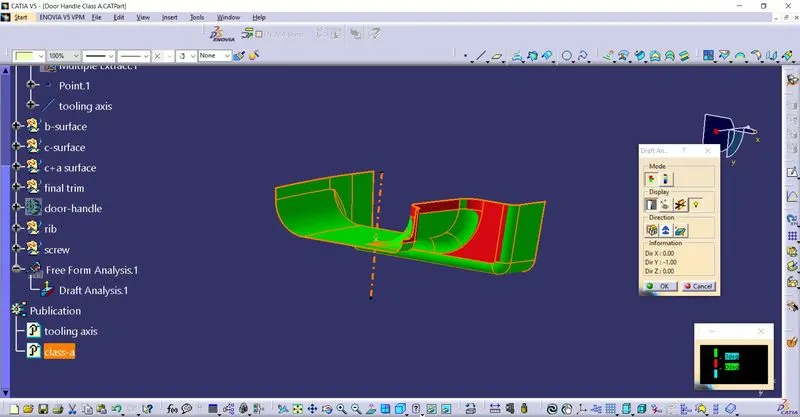
in the above image we can see clearly the red marks that means it is clearing the draft angle at 3 deg so we can change to 0.5 deg then it will clear shown below
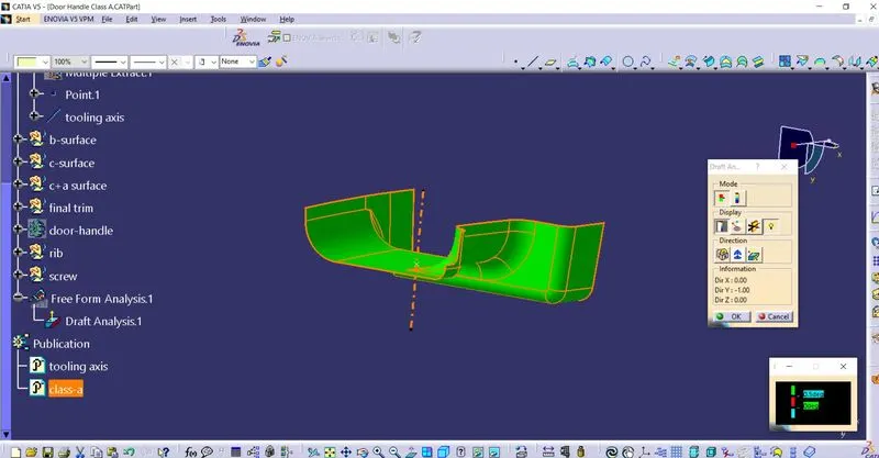
from the above image we can see that the your tooling axis is clearig the all draft angle with 0.5deg, so that we can proceed for the next operations otherwise we have to cxhange the tooling axis
next generating the surface-b
here we have the thickness of 2.5mm, so we have to take the offset of 2.5 mm the offset surface is shown below
offset
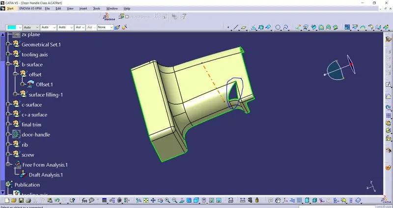
when we have offset the surface the we got thesome patches missing then we have to filling these patche highlighted using some commands
surface filling-1
in this surface filling 1st we have too remove the exsiting radius to fill the complete radius, for removing the radius we have to etract the surface using the multiple extracts and some command created b-surface
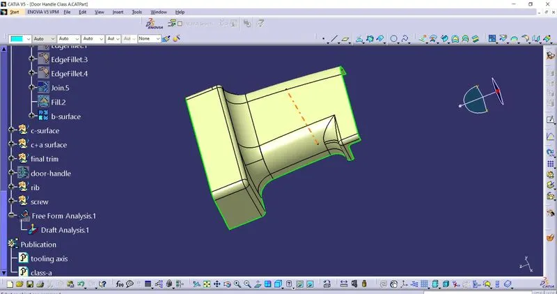
c-surface
now we have to create the c-surface from the class-a surface by using the sweep command at 90 degrees from the class-a surface and join the class-a and class
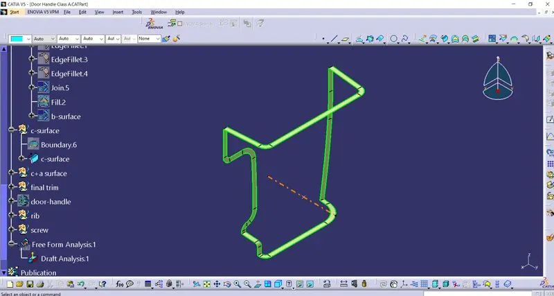
need to create c+a surface
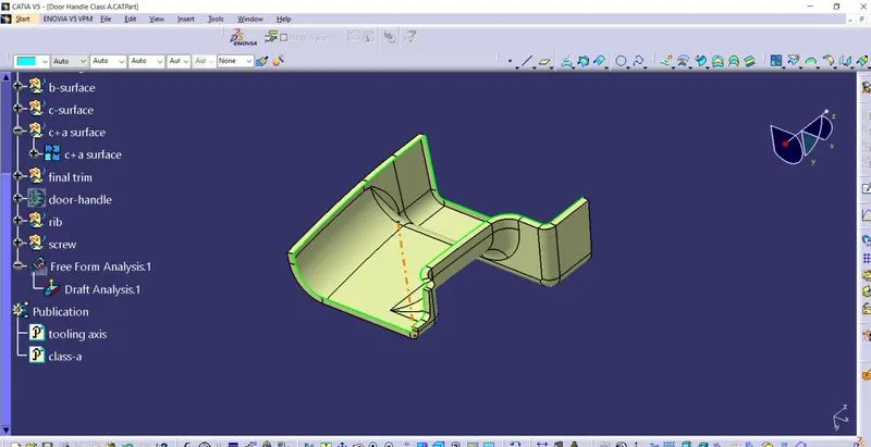
hen trim the class-a+c surface with the class-b surface the closed surface will be formed the apply solid by using the closed surface command
closed surface
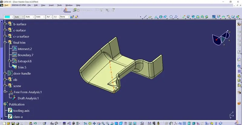
when the closed surface is done then then applying the closed surface command looks likes below
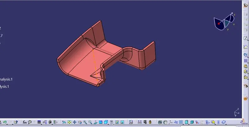
now we have start creating the rib design and screw design
then we have to extract the face where we have to form ribs the made the sketch on it as per requirement
sketch for the ribs
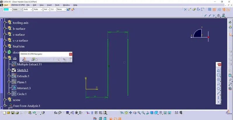
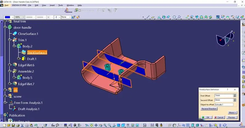
then by using this sketch create the extrude surface and using the thicksurface command make that extrude surface to 1mm thickness that from the main body thickness 2.5 40% thickness of 2.5 is 1 mm
thicksurface
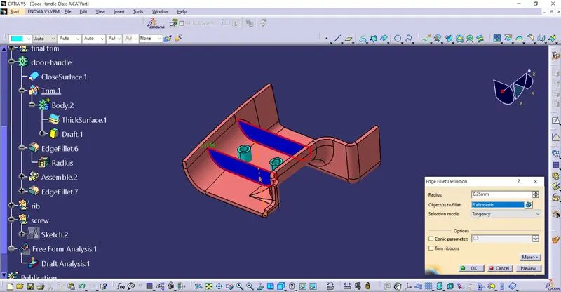
then trim those extra edges usin balooen operation for complete rib design and apply conditions like draft angle 0.5 per side radius, rib root thickness and height
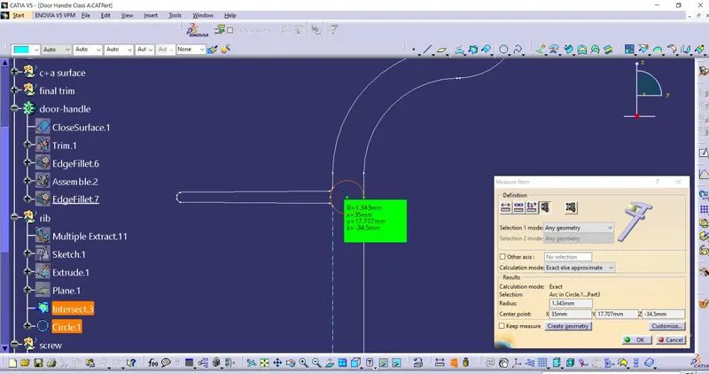
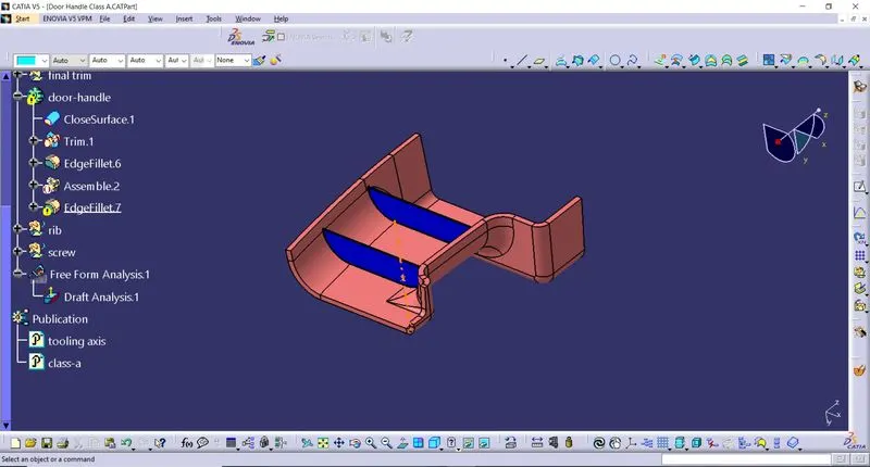
next screw bosses design
same like the rib create the sketch for the screw on the same plain
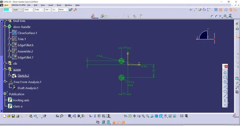
pad the sketch upto 3:1 of thickness is 7.5 and apply draft and radius to it
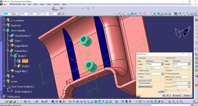
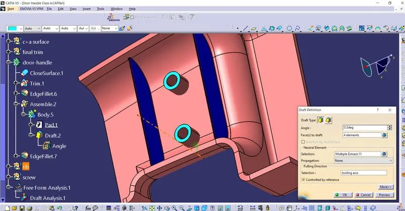
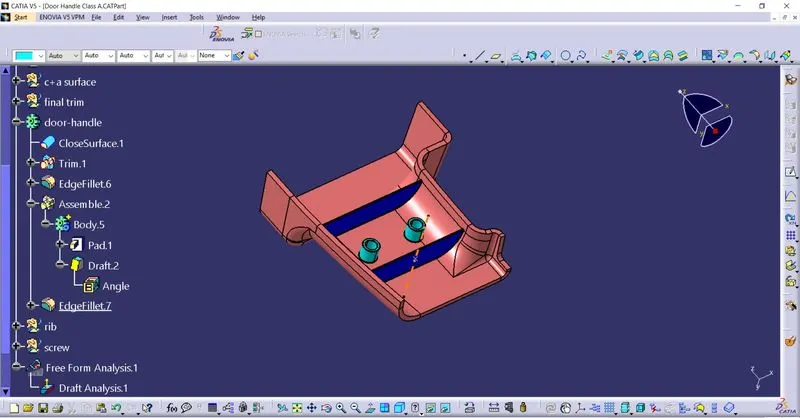
the final view of the door handle with ribs and screw bosses looks like below