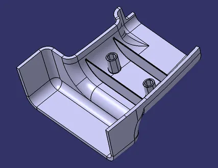
Week 9 - Attachment Feature Creation (Ribs & Screw Boss) - Challenge 1
Objective:
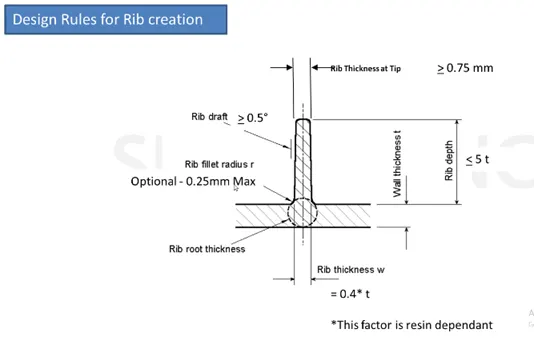
Create the rib for the Drill Handle considering the design rules mentioned.
Creating Tooling Axis:
The direction in which a part is pulled out of a mould is known as the tooling direction. Basically, the mould is constructed out of two independent components. You have the Core side and the Cavity side. The Dye line or Tooling Direction is when the Core separates from the Cavity.
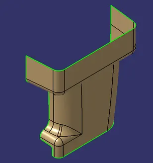
- First, Check the given surface for any gaps using Boundary command.
- Extract the Boundary.
- Find the correct tooling axis where the material don't interfere with the tooling axis and all the elements can be created
- Create bisecting line with the two lines and point to create a tooling axis.
Draft Analysis:
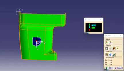
You can determine whether the part you drafted will be simple to remove using the Draft Analysis tool. In this kind of analysis, zones on the investigated element are identified by colour ranges where the deviation from the draught direction at any given place corresponds to predetermined values.
Class B Surface:
- Extract the surfaces from the class A using multiple extract and untrim them.
- Use Extrapolate to make sure that all the untrims are properly intersected to trim and offset the surfaces to 2.5 mm to create the thickness.
- Trim the extra surfaces using trim command.
- Perform trims one at a time so that it will be clear to understand
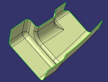
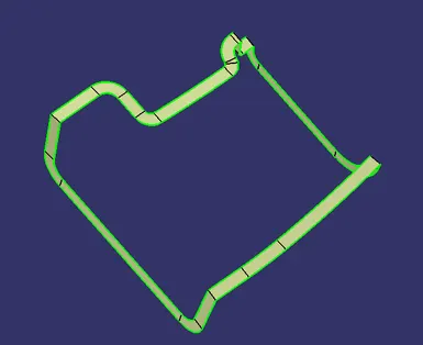
Claass C surface:
- Extract the boundary from the class A surface using boundary command.
- Using disassemble tool to divide the boundary as the boundary contains domains.
- Use sweep command to create C surface.
Now. Join the Class A surface, Class B Surface and Class C surface using options such as Join and trim and get a closed surface.
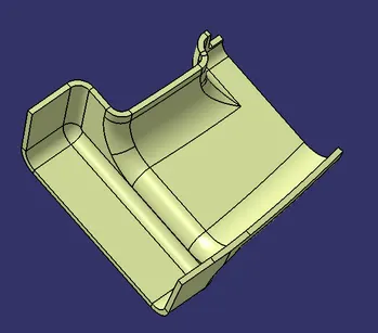
Now create the solid component using close body command in part workbench.
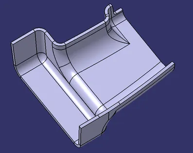
- Now Draw a sketch for ribs and screw bosses.
- Keep the design consideration for ribs and screw bosses while designing.