Week 9 - Attachment Feature Creation (Ribs & Screw Boss) - Challenge 1
The draft analysis is given to body inorder to avoid the scratches on the surface due to friction, also it allows for the part to release from the mold easily.
The minimum draft angle is given 0.5 degree and upto 3 degree is accepted.it is given with respect to tooing axis.
Drafting is done on C surface which connects A and B surface.
The Draft Analysis allows the user to easily analyze a part for proper draft angle. A Draft Angle describes the amount of taper for molded or cast parts perpendicular to the parting line.
during drawing, Initially we have given the A surface. First step is to draw the tooling axis by finding the most appropriate direction and using the bisection of tooling axes along X and Y direction by intersecting method,if needed. By inersecting the a suface and a plane , we get the line along it. we can give the drat angle on a body if there is large flat surface or on a circular hole if any.
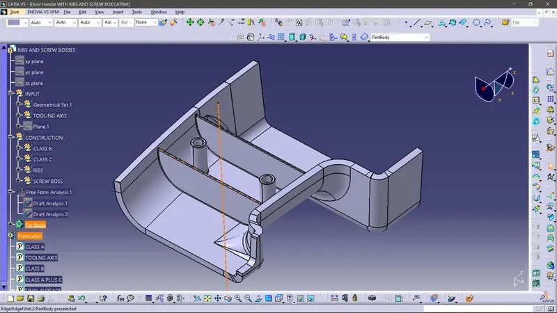
In Door handle we created the tooling axis by selecting and extracting a surface and draw the line in along y axis. and name it as tooling axis and published it
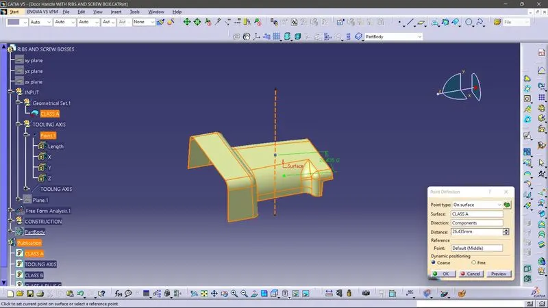
Draft analysis
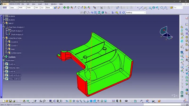
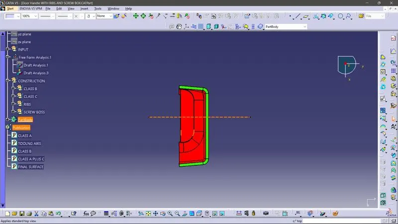
During the draft analysis we give the limits of 0.45 degree and 0 and negetive ,then give different colours to notify , here we give green ,blue, red. and then we select the compass button and drag it into the tooling axis and matches.
draft analysis of A surface
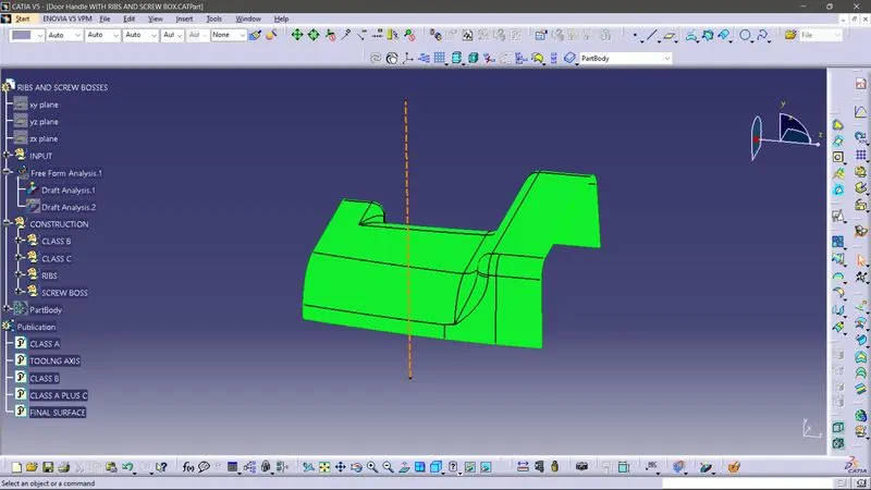
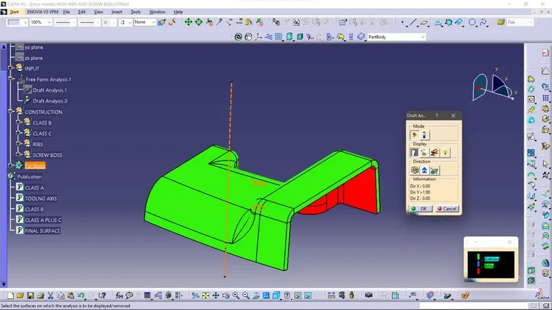
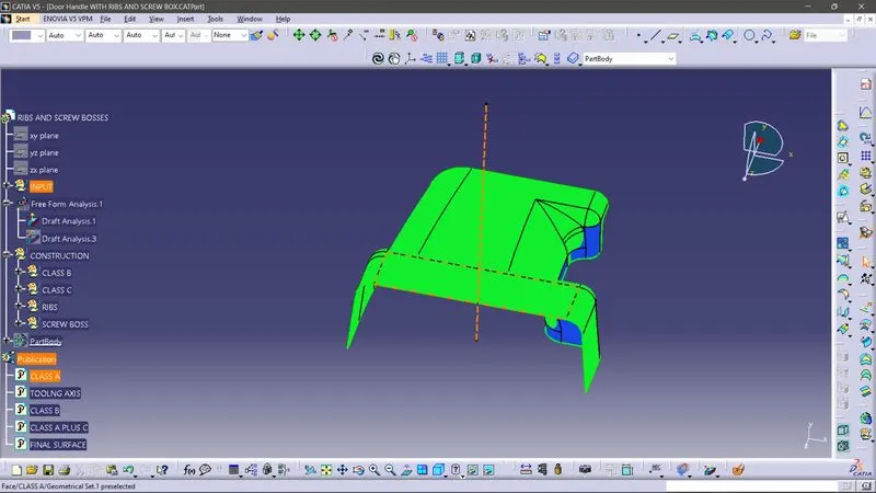
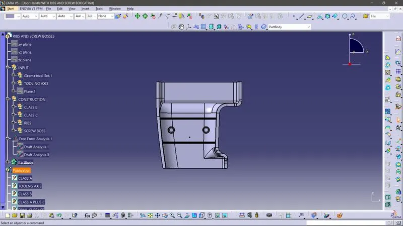
by inverting the draft analysis we can check the B surface features also.