Week 9 - Attachment Feature Creation (Ribs & Screw Boss) - Challenge 1
RIBS AND BOSS
RIBS- RIBS are generally used for giving stability to a product like if somewhere product bend at some angle at that place we provide ribs for that place to avoid bending
Ribs have some specifications or rules that we must follow while creating them
let's assume t is the thickness of the part
Maximum wall thickness =1.3*t
Minimum thickness at rib tip =.75mm
Minimum draft =0.5
Rib height =5* wall thickness of the component
Rib should follow the tooling direction
SCREW BOSS - Screw bosses are used to attach some parts to the component
like Ribs, Screw also has some specifications like
Hole = 0.3*t
W=0.6*t
Rib fillet radius= 0.25 mm
Draft angle =0.5
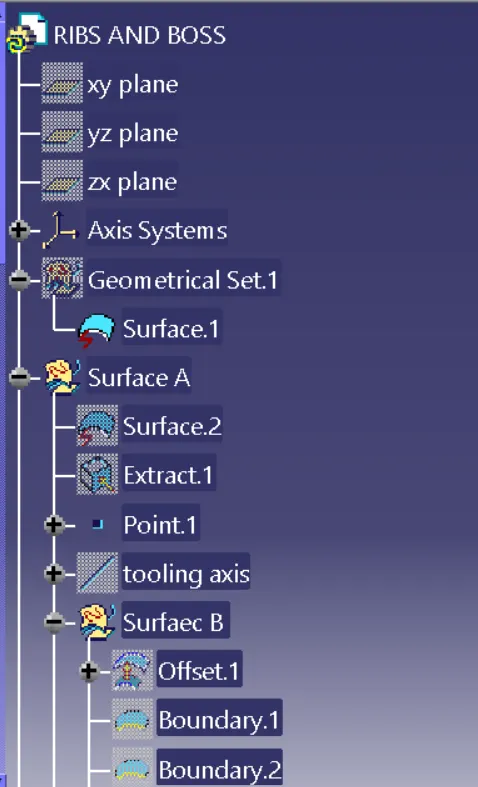
Surface A is given by engineer that we can work upon them
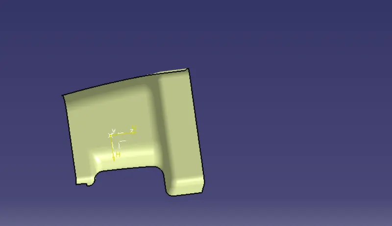
SURFACE B- Surface B where we can do all engineering processes like attaching Ribs screws etc.
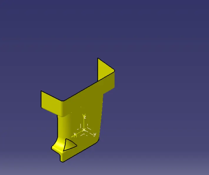
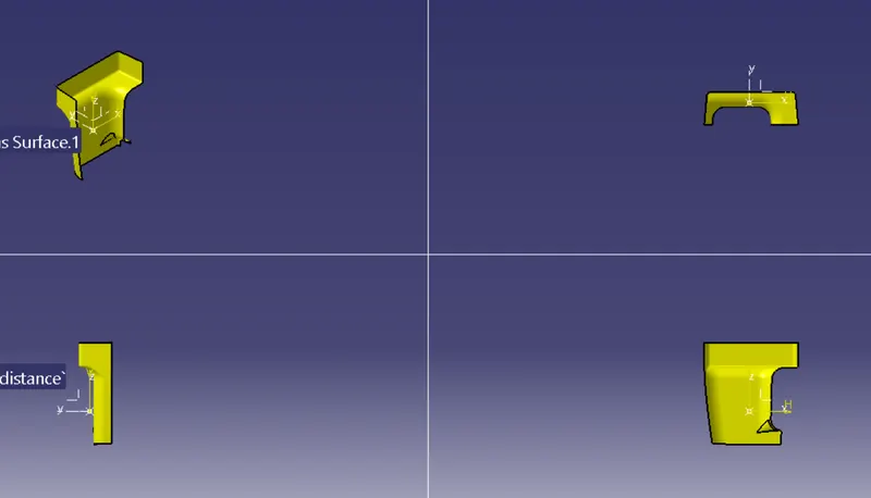
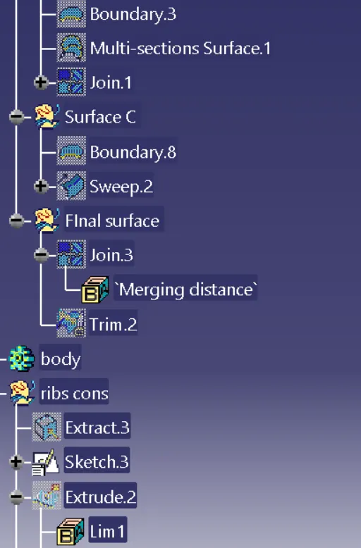
SURFACE C- Surface C is used to attach and b surface ,
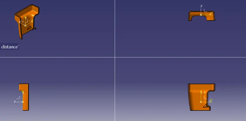
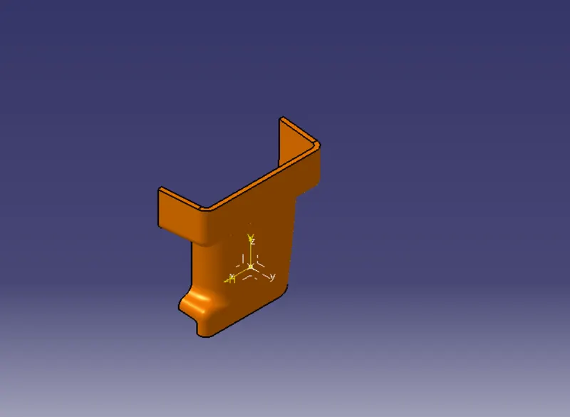
RIBS AND SCREW BOSSES
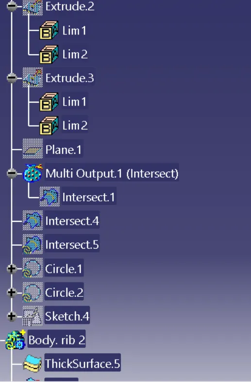
STEP 1- First we have to create a sketch for Ribs and extrude them after that we have to thicken that surface by using thicken command
used command -thicken surface ,extrude, line
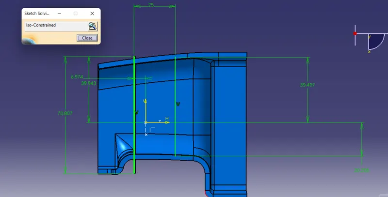 and use output command for that
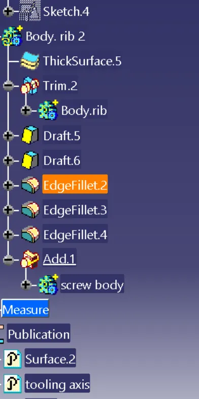
Step 2- In step 2 as per specification like draft angle and edge fillet and height =5*t given by using command
Step 3 - In step 3 by using boolean operation unitrim we remove excess material and after that we add them to main body, the draft angle is inverted to the body draft angle
same procedure we follow for screw bosses
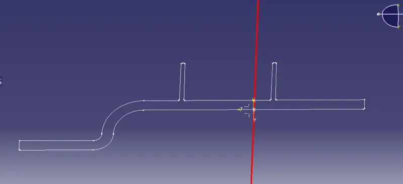
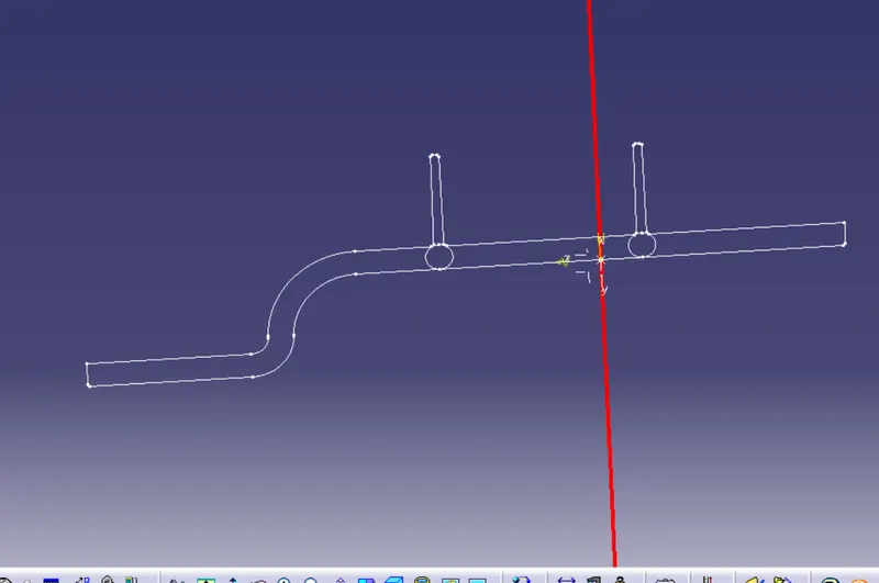
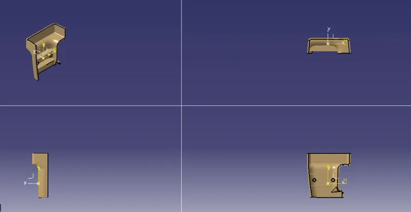
multisection view & Iso
TREE STRUCTURE