Week 9 - Attachment Feature Creation (Ribs & Screw Boss) - Challenge 1
Objective: To design a rib and screw bose.
Tooling Axis:- The direction in which mold opens or Core and cavity get separated, is called the Tooling axis.
Phase 1:-
In phase 1 we import Class A surface in Catia. That Class A surface may be in the different part surfaces, so we join them using JOIN Command in CATIA. For confirmation of joining we use BOUNDARY command, If boundary shows no error then we go for phase 2.
Phase 2:-
In Phase 2 we create Tooling axis of the product then we do draft analysis of it. We create a dummy tooling axis by visualizing the product. We choose dummy tooling axis such that products manufacturing will be easy. In our Base cover along Z axis will be our dummy tooling axis.
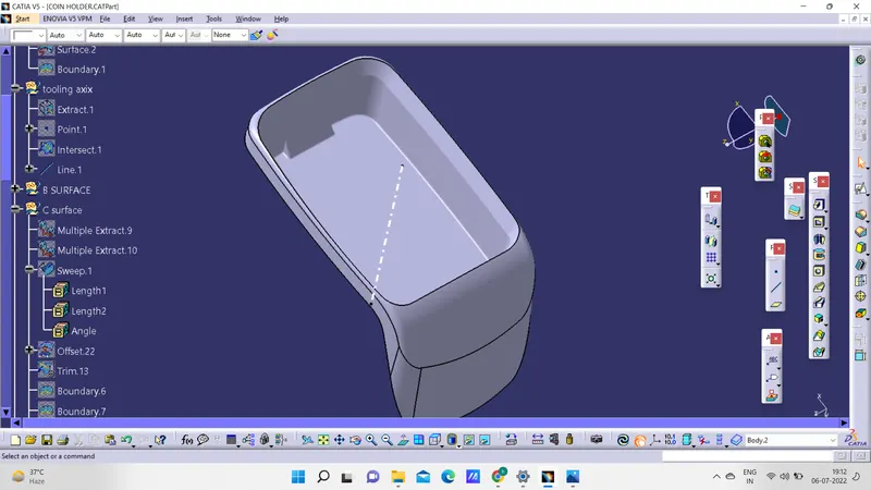
DRAFT ANALYSIS
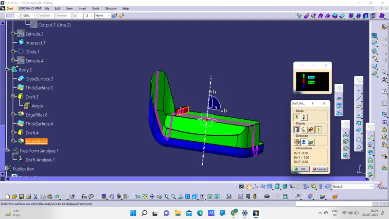
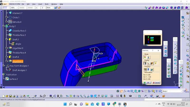
NOW EXTRACT BASE SURFACE
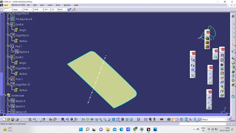
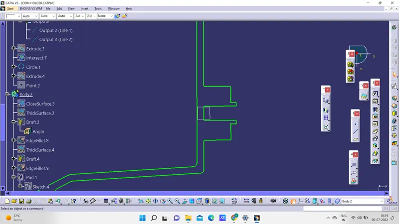
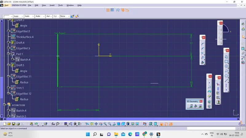
SKETCH THE LINE AND EXTRUDE IT FOR 12.5MM OUTWARD AND 1MM INWARDS THICKEN IT FOR 1 MM
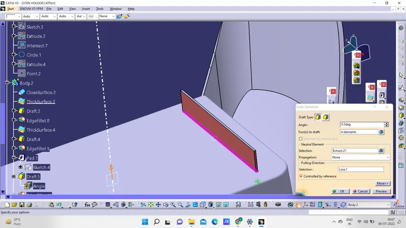
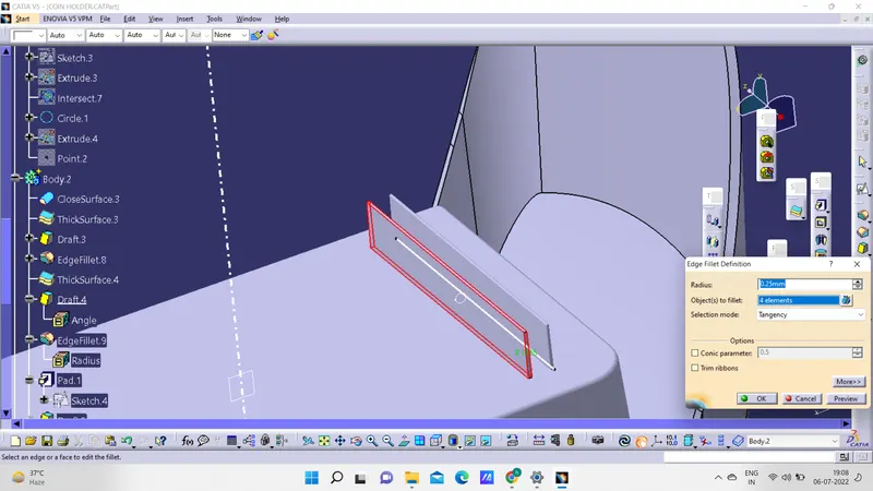
PROVIDE DRAFT ANGLE OF 0.5 DEG AND 0.25 FILLET TO ALL FACES
REPEAT ALL THE STEPS TO CREATE ONE MORE RIB
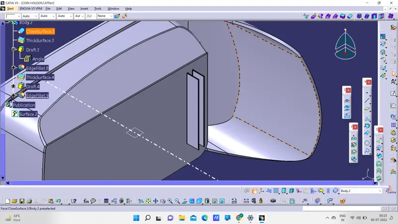
RIB ROOT ANALYSIS
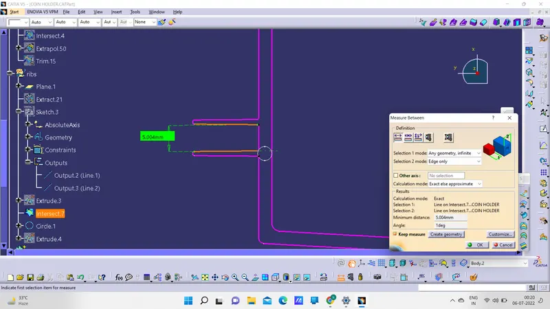
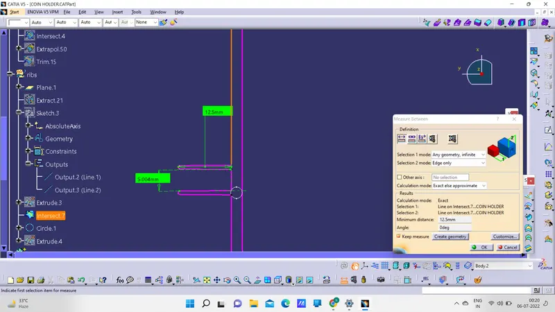
CREATION OF SCREW BOSE
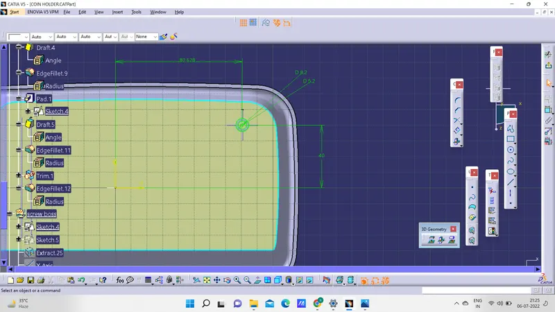
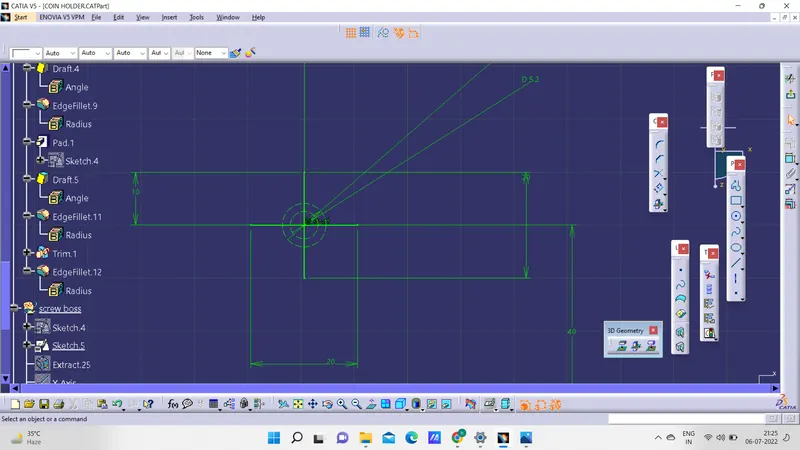
PAD THE SKETCH 12 MM OUTWARDS AND 1 MM INWARDS
AND REMOVE THE INSIDE SURFACE BY UNION TRIM TO GET THE SCREW BOSE
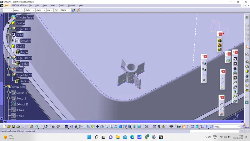
ROOT ANALYSIS OF SCREW BOSE BY INTERSECTION