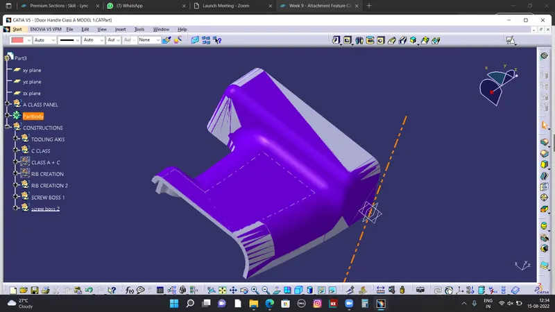
PROJECT 17 - CATIA V5 - ATTCHMENT FEATURE CREATION (RIBS & SCREW BOSS FOR TRIMS)
Aim:
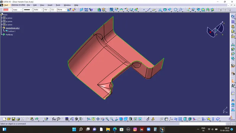
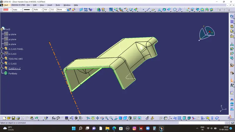
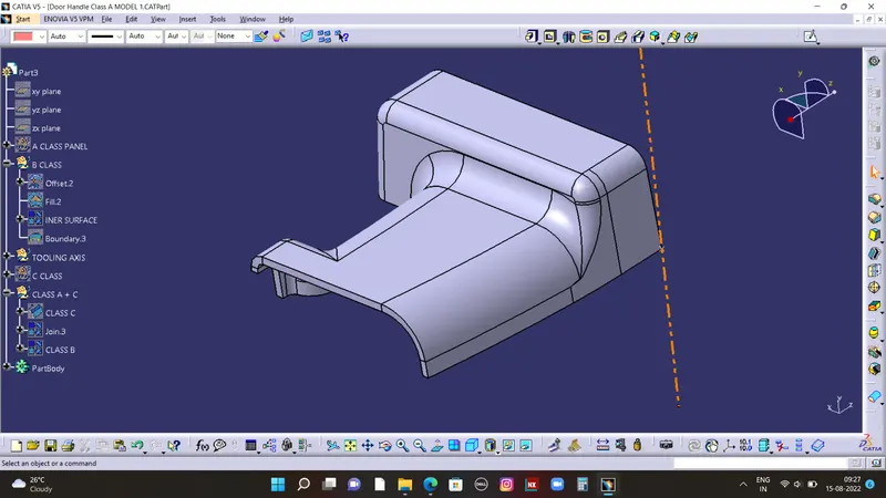
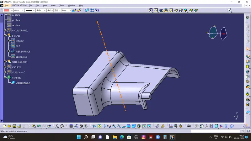
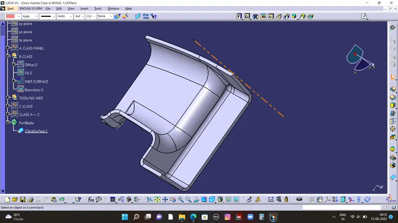
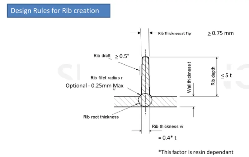
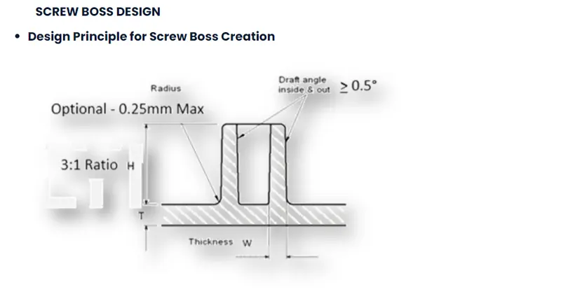
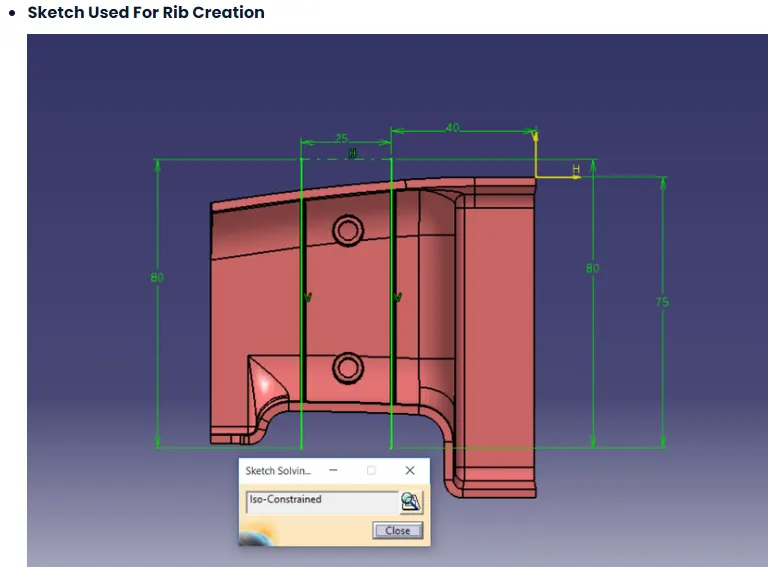
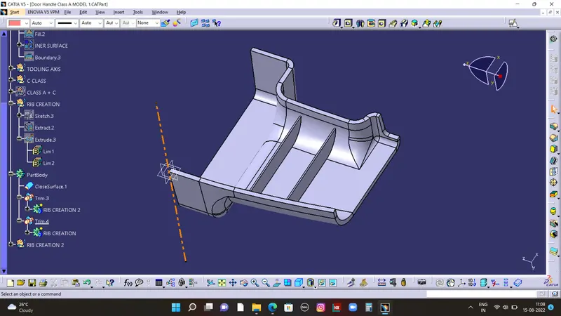
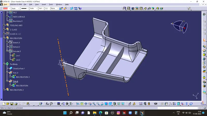
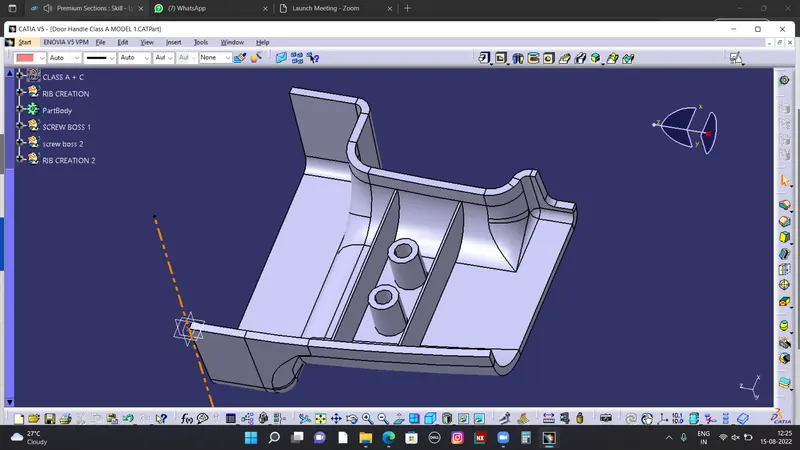
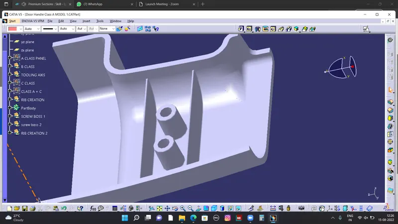
To Create a DRILL HANDLE attach with B side features Ribs & screw
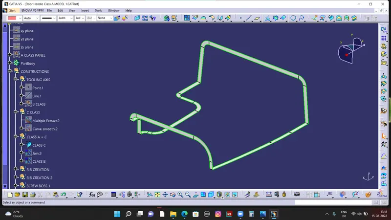
boss plastic component design throught the given CAT Part file from Class A surface To
make a Class B & Class C Surface and final component.
Used via
Catia V5 software- tools used given below,
Point through on the center of the surface
Axis creation
Line in point direction
Bisecting line
Intersection
Tool Axis
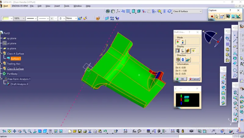
Draft Analysis in Free from Analysis
Untrim
Boundry
extract boundary
multiple extract boundary
Extrapolate
Offset
Trim
Join
Sweep command particularly with draft direction
blend
fill surface
Extruded surface Closed Surface
Thicken surface
Pad
Draft
Fillet
Tooling Axis creation:
It is defined as the direction in which the mold/core and cavity open. Then resultant tooling
axis is created using the bisecting method.
Selection of the direction of the tooling axis depends on the ease at which components ca
be easily ejected.
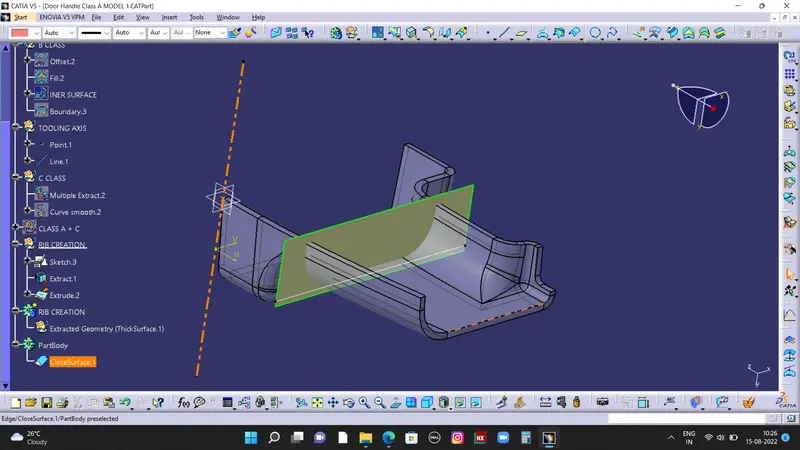
By analyzing the component the most easily ejectable direction is somewhere close to the
Z direction,(might be inclined to it) so we have made a sketch on the YZ plane of the Axis
System) to create a bisecting line considering the 2 faces which might be difficult to be
tooled.
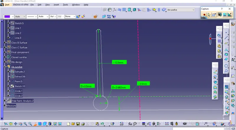
Taking the Thickness of the component to be 2.5 mm