Week 9 - Attachment Feature Creation - Challenge 2
Door Trim With Dog House
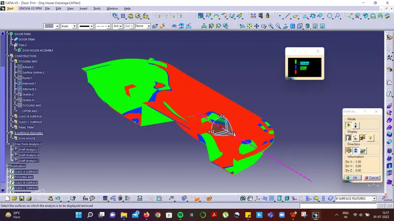
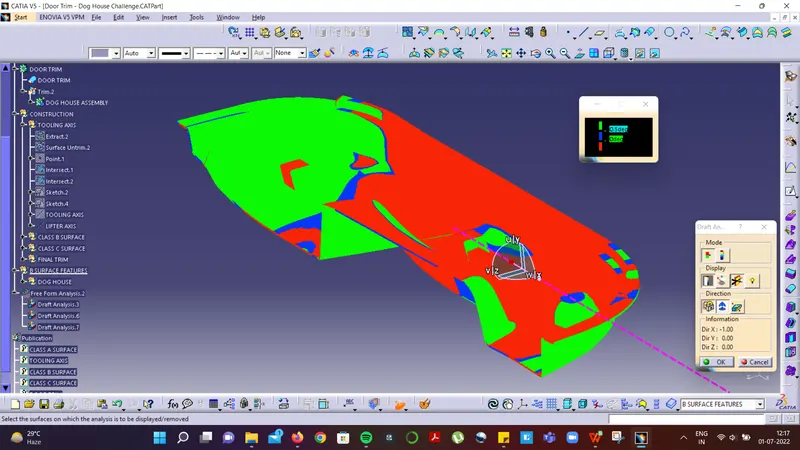
DRAFT ANALYSIS
As from the isometric view the following Door Trim Class A Surface is analyzed with x,y and z axis.
X axis tooling direction analysis - It can be seen that extra side core is required to clear the part hence the x axis for tooling cannot is not considered.
Y axis tooling direction analysis - It can be seen that all portion of the part is cleared through this tooling direction and hence the y axis is considered for tooling.
Z axis tooling direction analysis - It can be seen that additional tooling may require to clear hence the z axis based tooling is not considered.
Further, the bisecting method is used to create tooling axis along z axis.
BISECTION METHOD
TOOLING CLEARING X DIRECTION
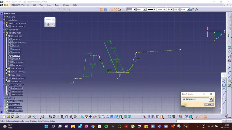
A cross section intersection along x direction is taken. Further the edges that are parallel or slant which may intersect with tooling axis is taken into consideration and elongated line is created for respective edges. Further, using line command and a line is drawn and respective angle is given with respect to vertical axis according to portion of surface to be cleared. The following line clear shows that the following edges will clear.
TOOLING CLEARING Z DIRECTION
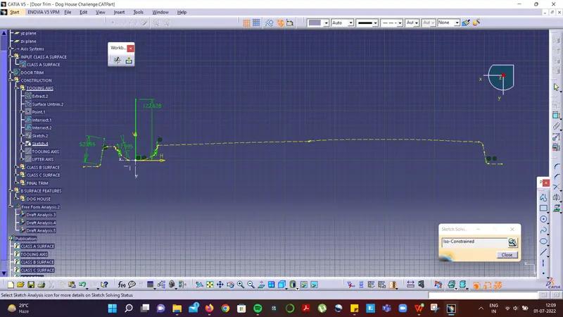
A cross section intersection along Z direction is taken. Further the edges that are parallel or slant which may intersect with tooling axis is taken into consideration and elongated line is created for respective edges. Further, using line command a straight line with respect to vertical axis is drawn. The following line clear shows that the following edges will clear.
TOOLING AXIS
The tooling axis (orange line) is created by selecting the line command and bisecting the tooling clearing line in x and z direction and a point. The tooling axis along y axis is achieved. The tooling axis is analzyed by the draft analysis where minimum draft angle is entered here it is 3 degree and the tooling direction is set upwards. Thus giving clearence in highlighted green.
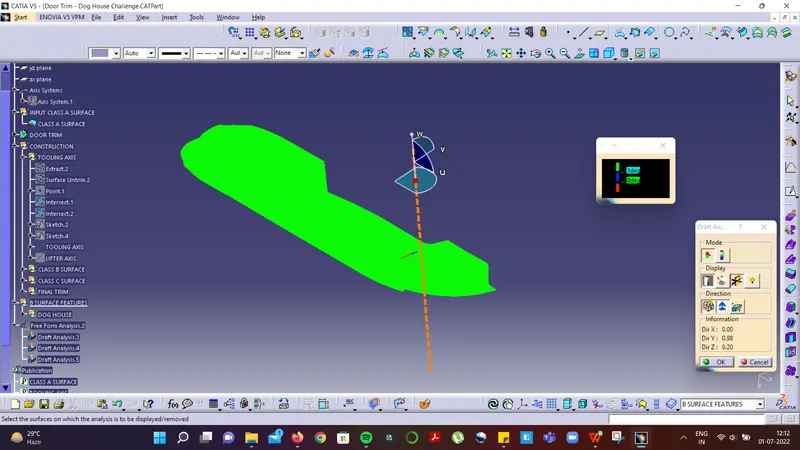
Tooling Axis
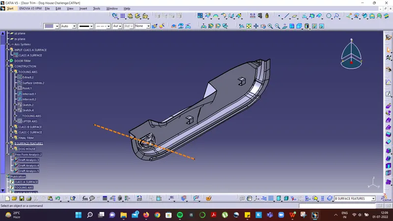
LIFTER AXIS
The Lifter axis is created by selecting the line command and a point. The lifter axis is achieved along tooling axis in this case (pink colour line). The lifter axis is analzyed by the draft analysis where minimum draft angle is entered here it is 0.5 degree and to clear the inner section of dog house. Thus giving clearence in highlighted green.
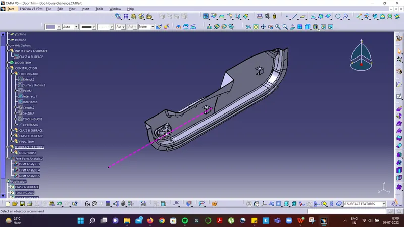
DRAFT ANALYSIS CLASS A SURFACE (3 DEGREES)
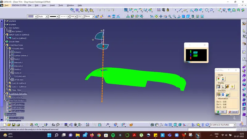
A smaller portion of in class A surface is not cleared as highlighted in red 7 blue.
DRAFT ANALYSIS SOLID MODEL (3 DEGREES)
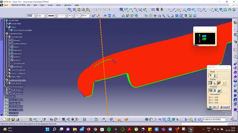
DOG HOUSE OUTER SECTION DRAFT ANALYSIS
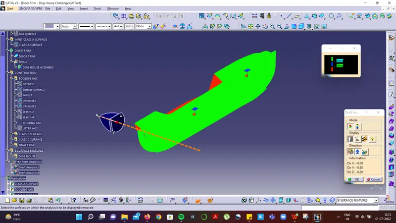
DOG HOUSE INNER SIDE DRAFT ANALYSIS (0.5 DEGREES)