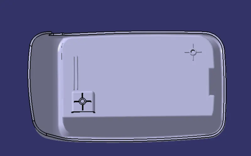
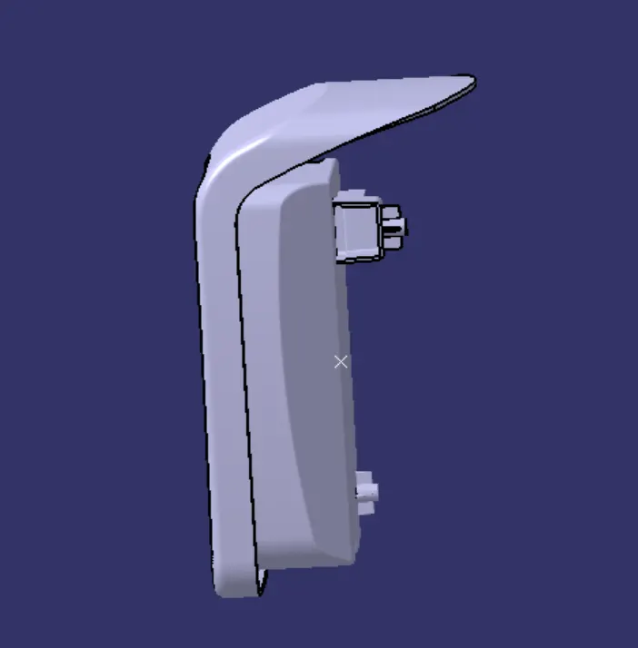
Week 9 - Attachment Feature Creation - Challenge 2
SCREW BOSS:
1)First make a positioned sketch on the z-x plane for the screw boss.
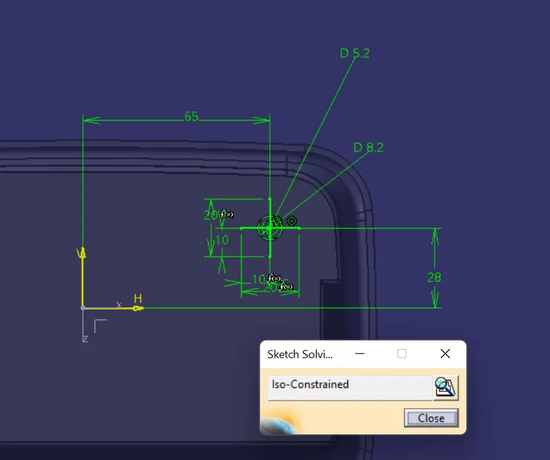
2)Pad the sketch and we get the cylinder which is initial screw boss structure.
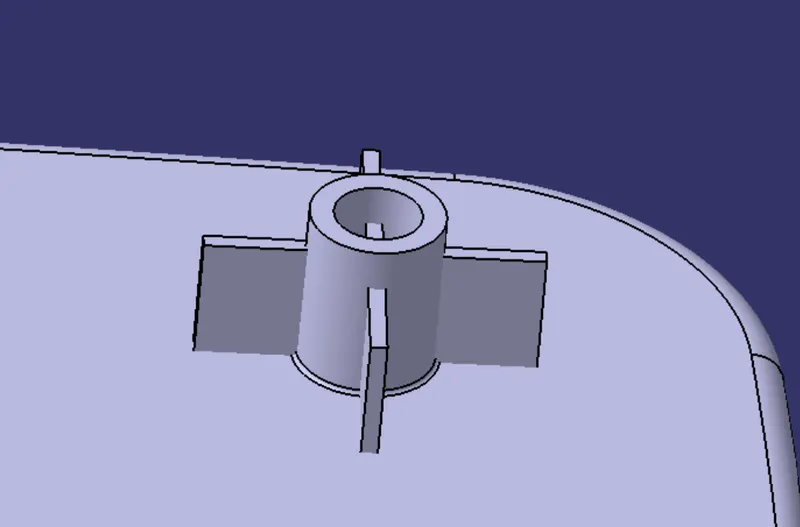
3)Draft both the cylindrical faces it with minimum 0.5 deg draft.
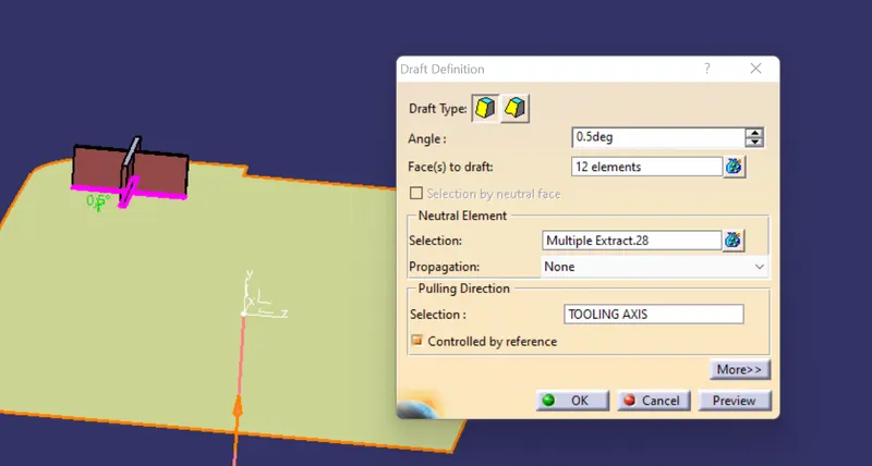
4)Make sure the wall thickness is in accordance with the design standards i.e. 0.4*t.
5)Also while giving height to the pad, give it within the limits.
6)To enhance the strength of the screw boss we make gussets which are rib like structure.
7)First make the sketch of the gussets as
8)Then pad the sketch with thick feature on and ensure that the resulting pad is in the middle.
Make sure the thickness is in accordance with the design rules of the ribs i.e. 0.4*t and also the height should not be more than 5*t.
9)Give draft to the gussets i.e. minimum 0.5deg.
10)Union-trim it with the screw boss and add/assemble it to the main model.
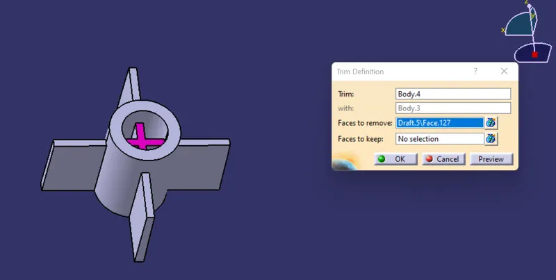
11)Give minimum edge fillet to it i.e. 0.25mm.

FOR DOG HOUSE:
We made a ditto screw boss for
1)Copy the existing screw boss.
2)Paste special in the main part file.
3)Translate it to the desired position.
steps:
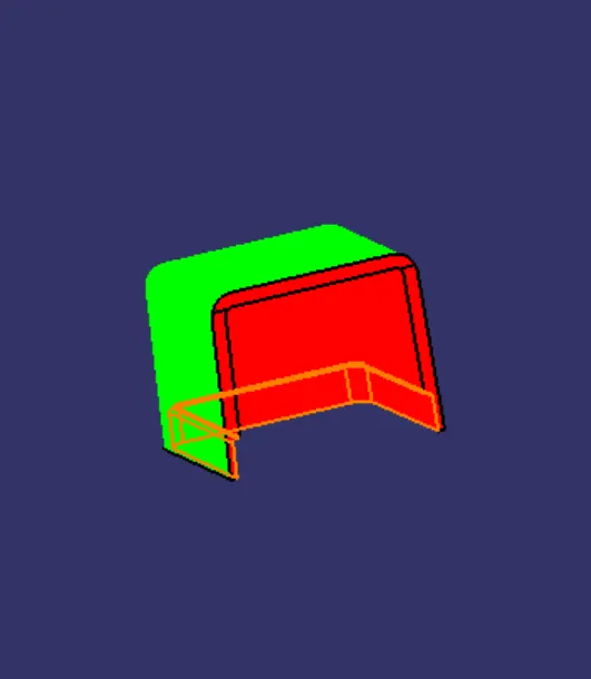
1)Make a rectangle to enclose the screw boss in it but make sure it is open from one side.

2)Sweep it with tooling axis as the pulling direction and give minimum draft of 1.5deg inwards.
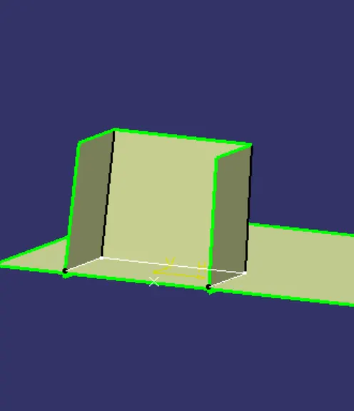
3)Enclose it from the top by using the off-set of extract of the base of class-A surface.
The offset distance determines the height of the dog house, so give it according to the design rules.
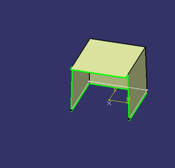
4)Go to part design and thicken the surface. Thickness should be according to the design rules.
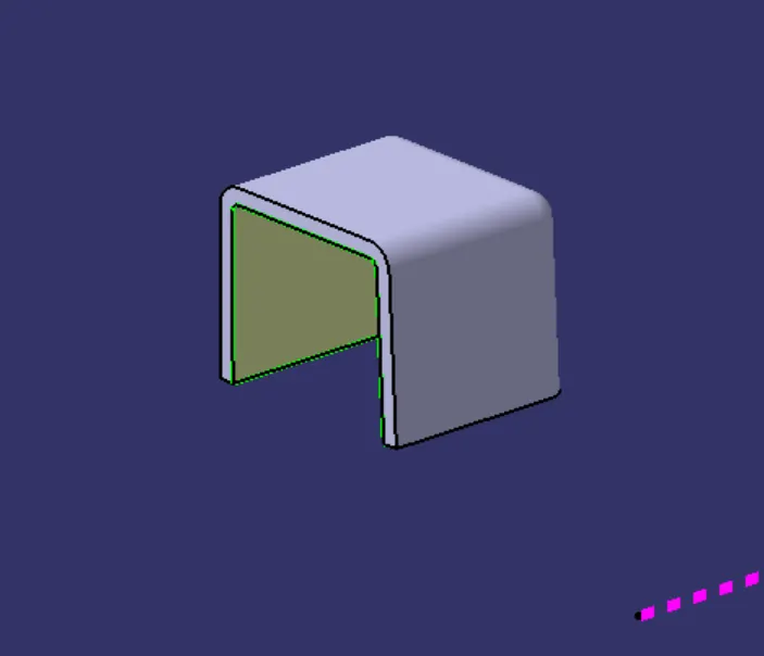
5)The inward face of the dog house should be drafted too, so give them a draft of 0.5deg.
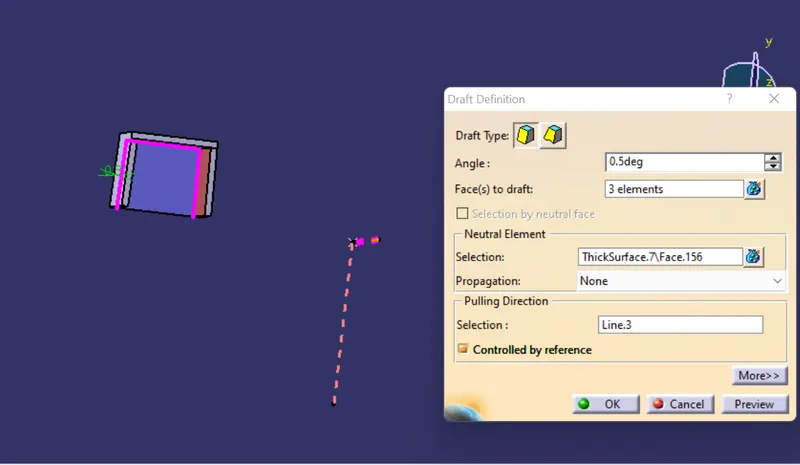
6)After this we have to design the sink saver at the bottom of the dog house:
7)Use the same extract of class-A, and offset it at the height of 3mm-6mm.
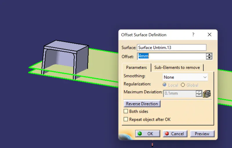
8)Extract the inside faces of the dog house and offset it outwards at 0.4*t.
This is the width of the sink saver denoted as “C” in the picture.
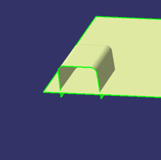
9)Trim them together.
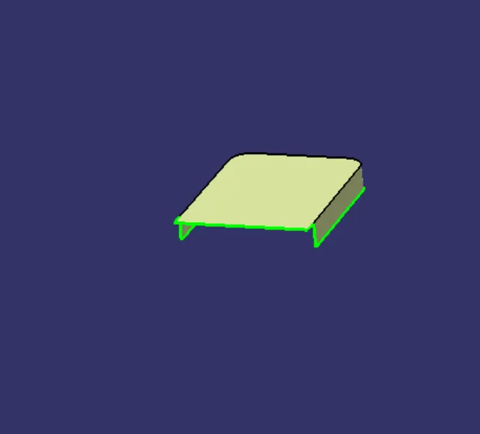
10)Go to the part design and split it with the model.
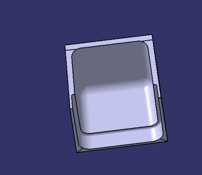
11)After that we will fillet the entire model of the dog house and add it to the main body.
12)Later we mount the screw boss on the dog house by translating it.
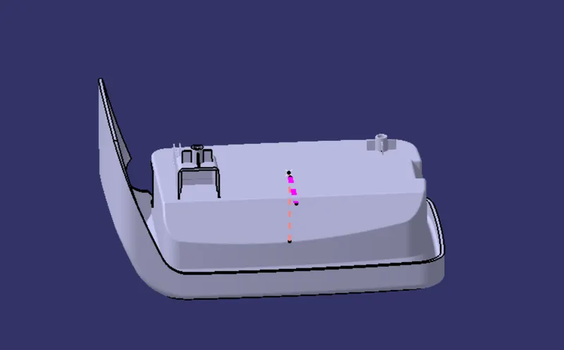
DRAFT ANALYSIS OF THE DOG HOUSE:
Draft analysis is done to prevent breakage of the component while ejection from the mould cavity.
It tells us which faces will clear according to the tooling axis chosen
1)Go to insert<analysis
2)Choose the compass and place it along the main tooling axis first.
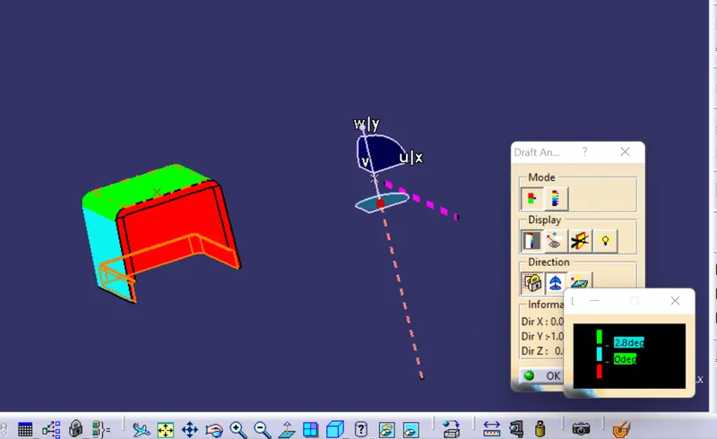
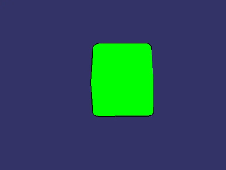
3)Lock it and click on the component. We will see colors on the component.
4)As we cannot run two draft analysis on the same component, use the compass for the side core tooling axis.
6)Lock it and click on the inner face. We will see colors on it.
7)We should get the desired faces in green color.
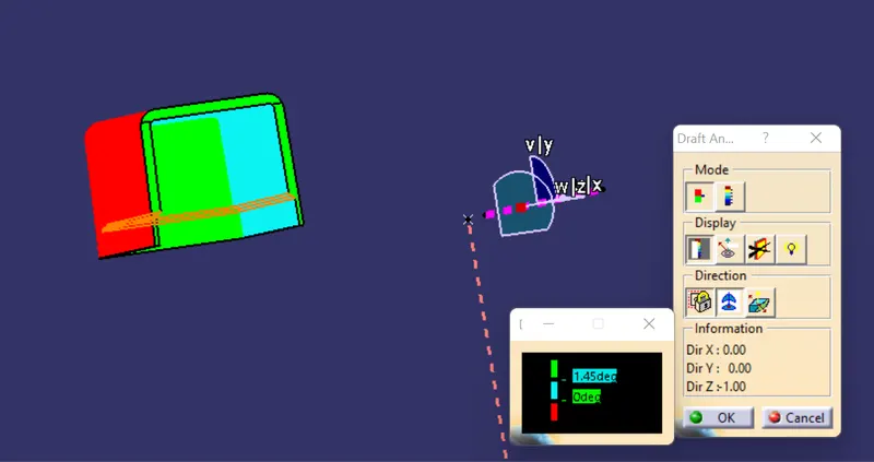
To understand the color code first we have to know the color scale. This option pops-up a small window where we can give three different colors to the three different values of. These values are nothing but the draft values that we can change.
The surfaces which are in green color means that the draft value it has is more than 0.5deg and it will not create problem.
The surfaces in blue have the draft value between 0deg to 0.5deg
The surfaces in red have the draft value in negative.
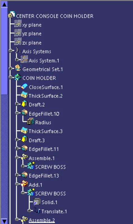
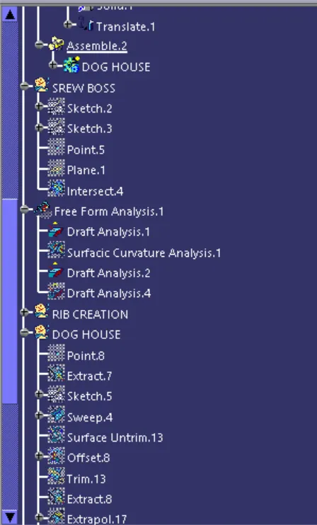
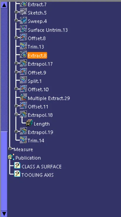
features tree image:
part model: