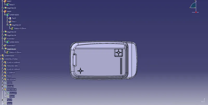
Week 9 - Attachment Feature Creation - Challenge 2
COIN HOLDER:
CREATING SCREW BOSS & DOG HOUSE FOR THE GIVEN COIN HOLDER:
SCREW BOSS-:
- Insert Geometrical set and name it as screw bose.
- Draw a sketch 2 circles small circles small circle dia 5mm & big circle dia 8.2mm.
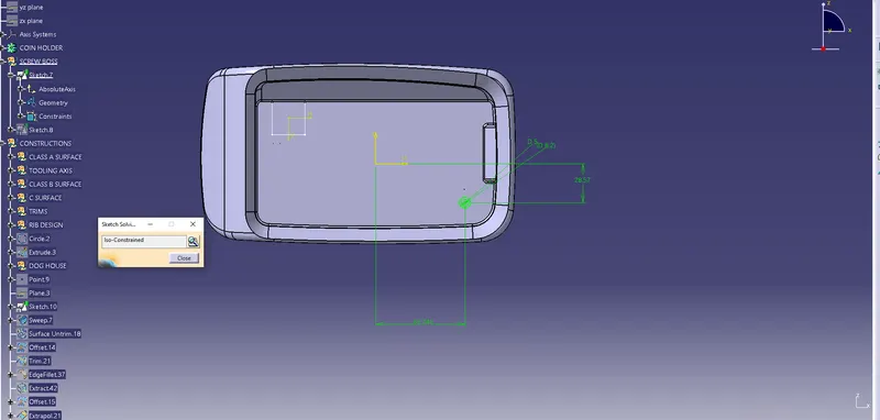
- Craete a pad for those circles as 12mm in first limit & 1mm in second limit.
- Add it to screw boss.
- Select draft command and draft the paded part
- Create another sketch 2 lines vertical and horizontal in center of the circle.
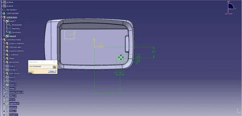
- Next step is Insert a body
- Pad the two lines for 10mm as first limit & 1mm as second limit, Thickness as 1mm and apply nuetral fiber.
- Draft the paded part.
- Apply union trim using the inserted body & remove the inner surface.
- Pick all edges and apply fillet.
- Copy the screw boss.
- Give paste special & Result link.
- Insert a body and name it as screw boss.
- Translate the screw boss in left bottom in the coin holder.
- Finally Assemble the screw boss body to coin holder.
DOG HOUSE-:
- Intially create a point in screw boss.
- Isolate the point.
- Extract the bottom surface of coin holder.
- Create a sketch a rectangular body which surrounds the screw boss in the part body.
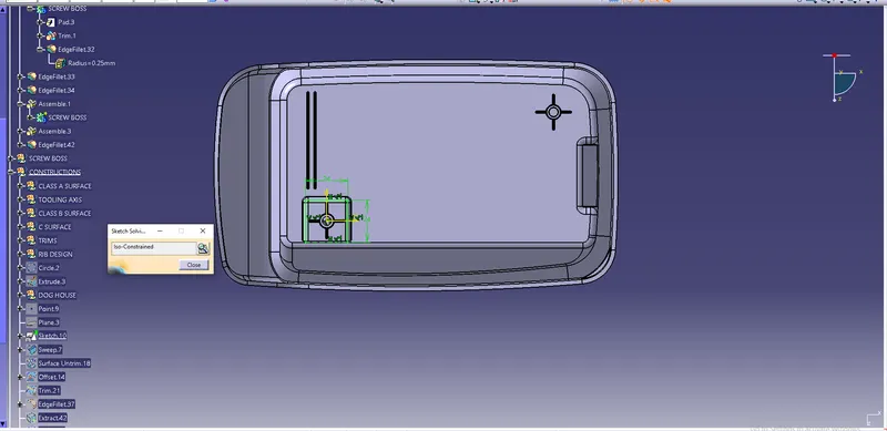
- Make as construction line the bottom line of rectangular.
- Insert a body.
- Sweep the rectangular body.
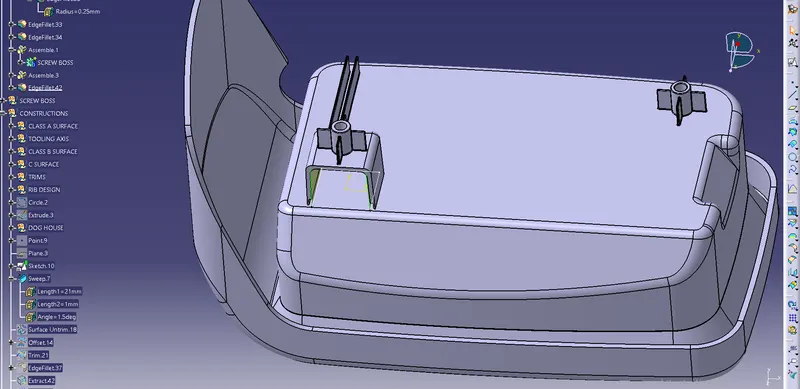
- Untrim the extarcted part.
- Offset the extracted part for 20mm.
- Trim it with sweep element.
- Go to part body and thicken it to 2mm.
- Assemble the thicken body into coin holder.
- sketch a plane.
- Change the geometical set of plane into dog house.
- Surface Untrim.
- Offset the untrimmed surface.
- Trim the sweeped part and the offset part.
- Apply the fillet in the required edges.
- Extract the trimmed part.
- Offset the extracted part.
- Extrapolate the part.
- Finally trim the offset and extrapolated surface.
- Place the screw boss up of the dog house by 22mm.
FINAL PART WITH SCREW BOSS & DOG HOUSE:
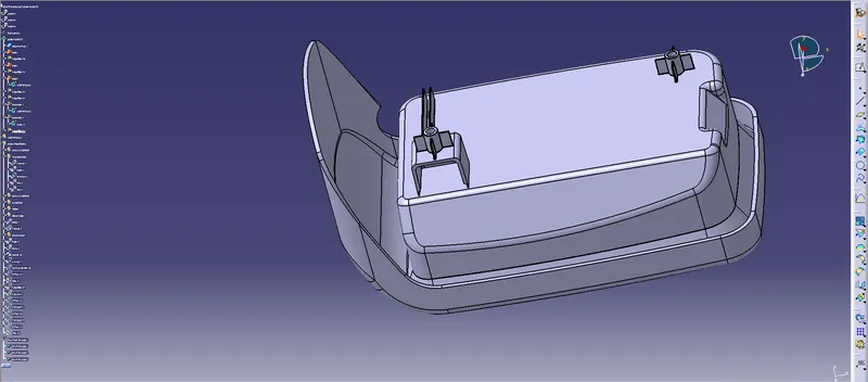
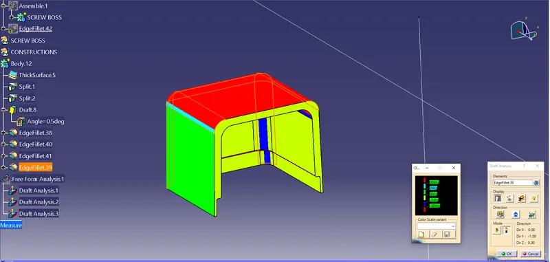
DRAFT ANALYSIS:
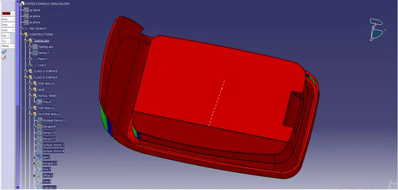
- This is the draft analysis for the first tooling axis.
- Green area is given as 2.9 degree.
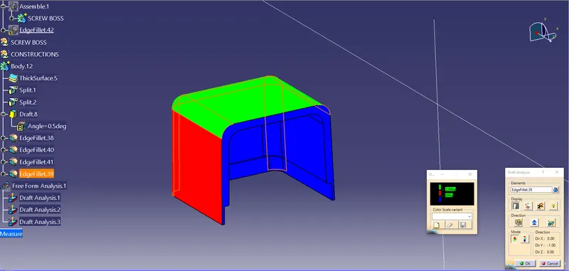
- This is the draft analysisfor the second tooling axis.
- Red area is given as 20degree & green as 0degree.
Types of views:
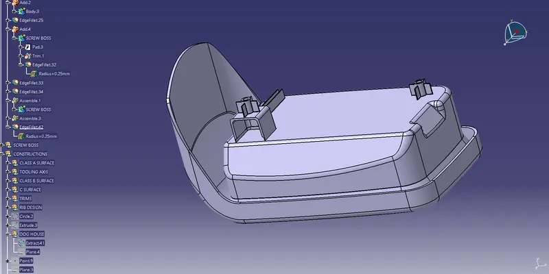
Isometric view-:
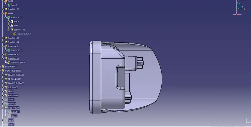
Front view-:
Top view-:
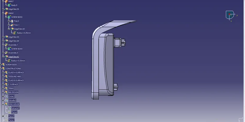
Side view-: