Week 9 - Attachment Feature Creation - Challenge 2
- Screenshots of the completed design in various orientations (Isometric, Front, Side, and Top View)
front view
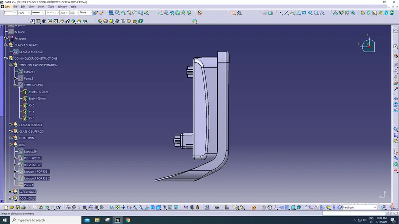
side view
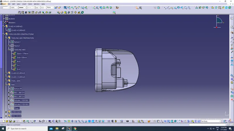
top view
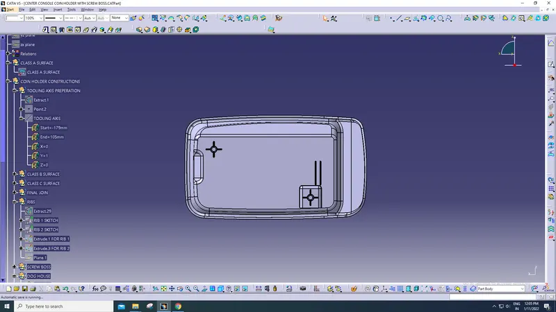
isometric view
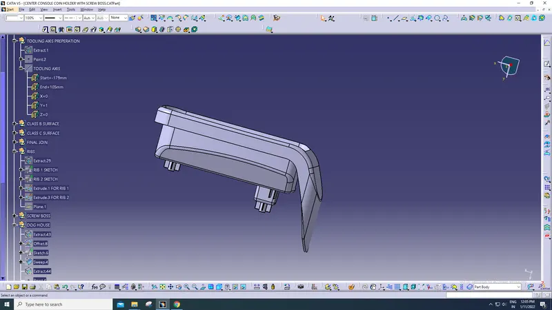
OBJECTIVE
to make a detailed report on explaining the tooling axis creation for coin holder
tooling axis is the direction in which the core and cavity moves to make a moulded component
every component which are going to be created must initally have a defined tooling axis , so that the component will get physically abled to be produced
procedure
initially the class A surface given as an input must be analysed in such a way that all the components in that part are properly joined and given to us as a single part and create a boundary for the class A surface , here the class a surface for coin holder is given
to create a tooling axis , first the tooling axis of the paticular part must me predefined , the predefenition of the tooling axis involves some factors , such as , there must' nt be any holes or slots in that face and it has a completed surface perpendicular to that axis
first we create a dummy tooling axis in z direction for this coin holder , which will give us an ease for identification of tool clearance on the other respective axises
then the analysis of the tool clearance on the x direction is made , for that we must have an axis system to do that
in that axis system , take zx plane , then make an intersection on that class a surface , from that intersection , create lines on the tapered sides of the intersectioned sketch , then from that lines created , create a bisecting line form them , which will result as the same dummy tooling axis we created , which says that the tool clearance on the x axis is perfect , if it really does .
the same procedure is done for the tool clearance in y direction , but the plane selection on the axis system will be on the yz plane
then a bisecting line between the lines of tool clearance in x and y direction is made , which will give as the tooling actual toolin axis for the coin holder
then make a publication for the fan cover and the tooling axis seperately , as mentioned
objective
to make a detailed report on explaining the draft analysis for coin holder
note : the actual draft for the every automotive plastic component designed must be 3 and above degrees
procedure
for making the draft analysis , insert the featuerd draft analysis tool , then place the compass in the created tooling axis to define the new current draft direction , then lock the draft direction by lock tool , then use the analysis under running point tool to measure the draft in the paticular position by moving the cursor along the coin holder , and set the angle in the colour scale varient as 3 degress . if the colour of the coin holder transforms into green colour , then the component is perfectely drafted to get manufactuered properly ,