Week 11 - Final project
DOOR TRIM PANEL
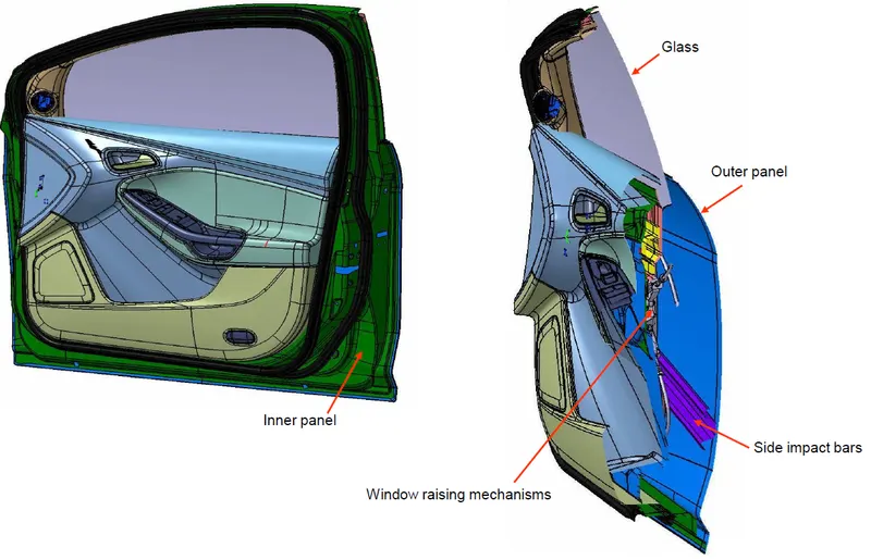
Door trim panel is the interference between the interior of the car and the inner workings of the car door . The door trim panel must be designed in such a way that it should withstand load and it must be more resistable during accidents or collisions and it must also satisfy aesthetically . In addition they must also conceal electric and mechanical components for operating locks , windows and other features . The thickness of the product must ne more or less equal to 2.5 mm . For ease of production , the door trim panel is divided into four parts and they are map pocket , lower substrate , door arm rest and bottle holder .
AIM
From the given input ( class A surface made by alias software ) we must create and improve class B and class C surface for every parts to get a complete thickened part by following the master sections which was also given as an input and to create attachment statergy for the product by perfectly following the design guidelines followed in automotive industries .
TOOLING AXIS CREATION
Tooling axis is the direction in which the core and cavity moves to make a moulded component
Every component which are going to be created must initally have a defined tooling axis , so that the component will get physically abled to be produced
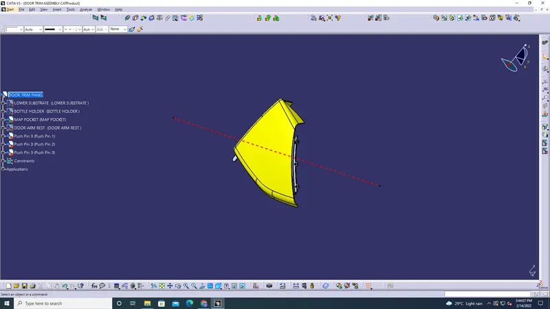
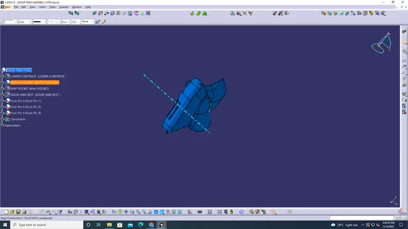
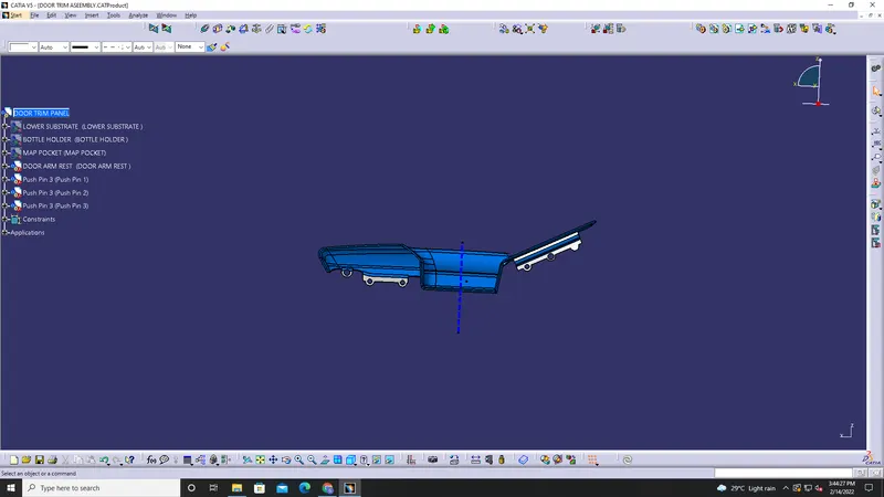
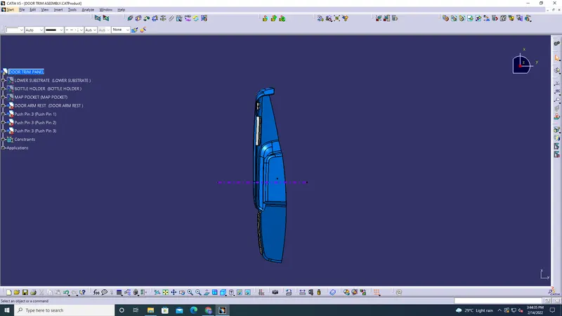
It is created by making a line which is perpendicular to the flat surface of the part , every part have its own tooling axis , some parts might have more than one tooling axis which is used to clear the other perpendicular flat surface of the part ( lifter axis ) , basically tooling axis is used to clear draft on the class c surface , nominal draft value used in automotive industry is 3 degree
Tooling axis of map pocket
Tooling axis of bottle holder
Tooling axis of lower substrate
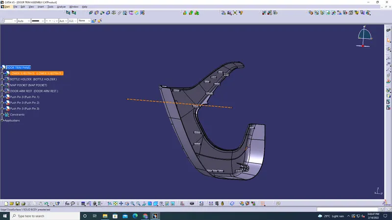
Tooling axis and lifter axis of door arm rest
CLASS A SURFACE
Class A is a term used in specifically in automotive Design . It describes the final production surface data for the aesthetic parts of the car .. simply class A surface is a surface which is visible to us physically , class a surface starts with a fully developed Design or a clay model
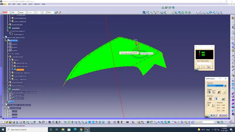
CLASS A SURFACE WITH DRAFT ANALYSIS FOR MAP POCKET
CLASS A SURFACE WITH DRAFT ANALYSIS FOR LOWER SUBSTRATE
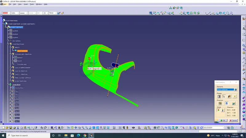
CLASS A SURFACE WITH DRAFT ANALYSIS FOR BOTTLE HOLDER
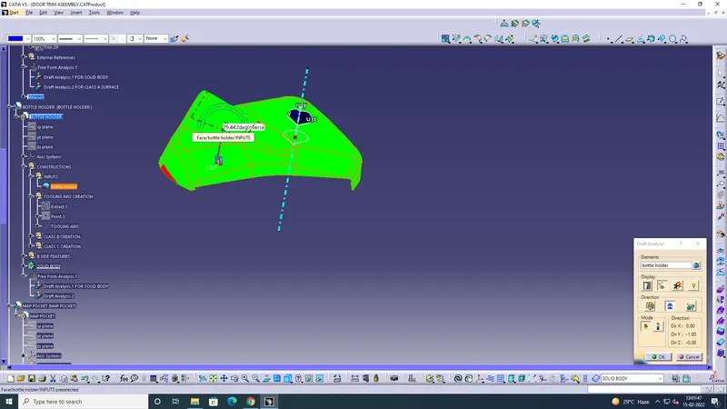
CLASS A SURFACE WITH DRAFT ANALYSIS FOR DOOR ARM REST
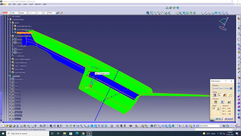
CLASS B SURFACE
Class b surface is a surface which contains all of the b side features or attachment features of the product , which is basically created by offseting the class a surface downwards to the class a , sometimes while offseting , the class a might not get properly offseted which give rise to some of the missing patches in class b surface , this must be improved by the design engineer . Here from the master section , it is known that the offset value made must be 2.5 mm ( which is the thickness of the plastic product )
Class B surface of map pocket
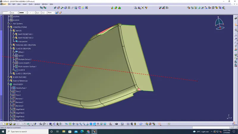
Improved class b
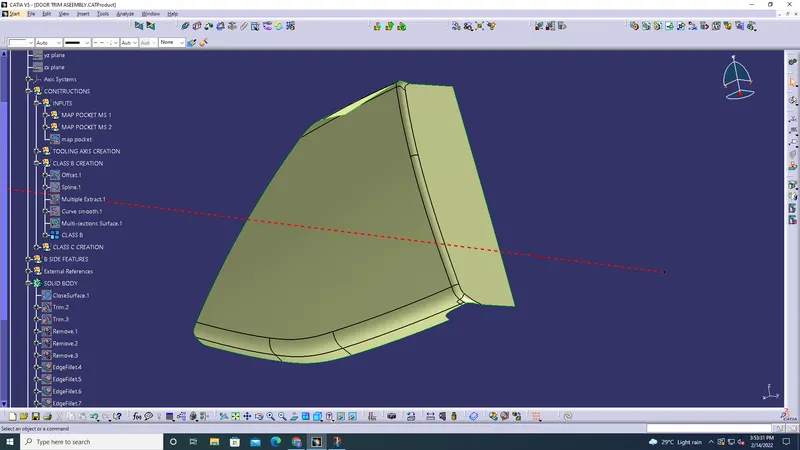
Class B surface of bottle holder
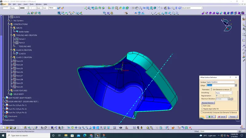
Class B surface of lower substrate
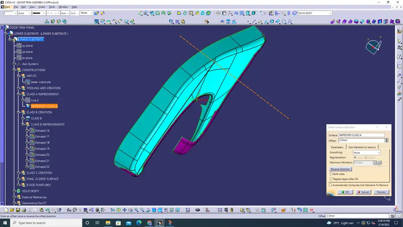
Class B surface of door arm rest
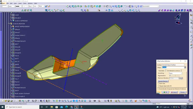
Improved class B
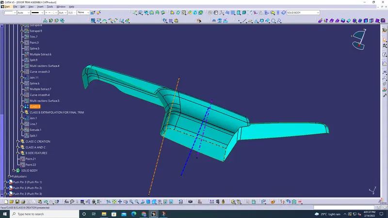
CLASS C SURFACE
Simply ,class c surface is the closing wall surface for the class A and B , this class c surface is created by taking boundary of the part and by using this boundary we sweep a surface with reference to the class a surface
Class C surface of map pocket
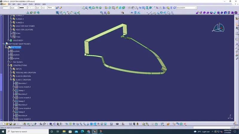
Class C surface of door arm rest
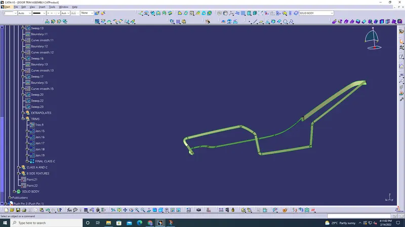
Class C surface of bottle holder
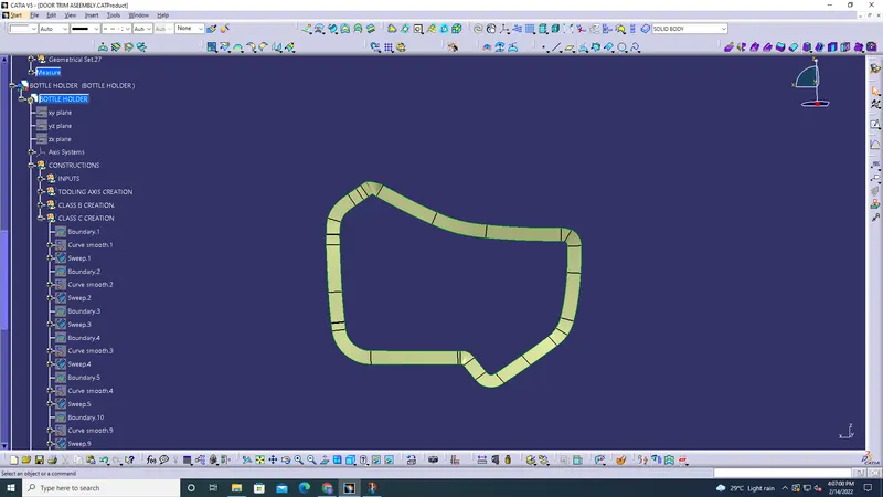
Class C surface of lower substrate
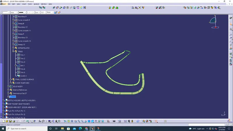
PROCEDURE FOR CREATING THICKENED PARTS OF THE DOOR TRIM PANEL :
Step 1 : Import the given inputs and then arrange then in the product workbench , first examine the class A surface and check weather it has any elevated patches in it , if it has , then improve it .
Step 2 : Then create class B surface by offseting the class a surface for 2.5 mm , if it creates any hole patches while offseting , improve it by closing the patches by using multi section command or fill command
Step 3 : Then create class C surface by taking the boundaries of the part and then by using sweep command create surfaces in such a way that it must create a perfect closed walls for the class A and B surfaces
Step 4 : Next join the class A and C surface by using join command ,
Step 5 : After joining class A and C , trim the class B surface with them , to create final closed surface , if it creates any boundary in the final closed surface , increase the merging distance to 0.1 while joining the class A and C , and extrapolate the class b surface if needed for proper triming .
Step 6 : Then go to part workbench , and by using closed surface command to the final closed surface for making it as a solid part .
Note : This procedure is same for map pocket , Lower substrate , door arm rest , bottle holder
FINAL CLOSED SURFACE
FINAL CLOSED FURFACE OF MAP POCKET
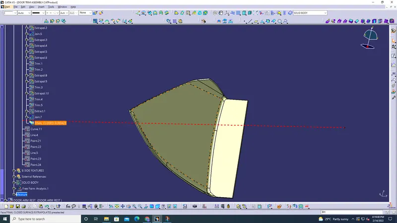
FINAL CLOSED FURFACE OF LOWER SUBSTRATE
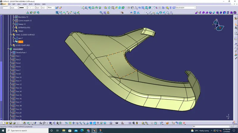
FINAL CLOSED FURFACE OF BOTTLE HOLDER
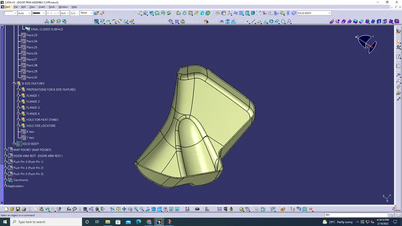
FINAL CLOSED FURFACE OF DOOR AREM REST
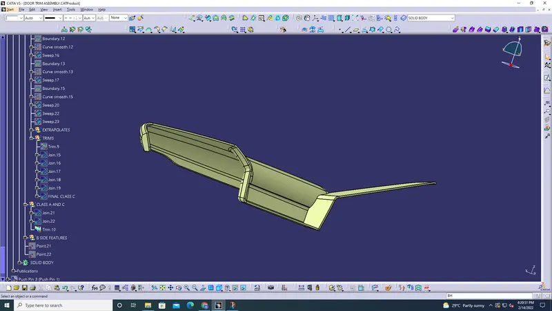
B SIDE FEATURES OR ATTACHMENT FEATURES
1 Flanges
2 Heat stakes
3 4 way locators
4 Dog house
5 Ribs
FLANGES
flanges are used to increase the length of part , which is to get attached to the neighbouring part by heat stakes or other attachment features .
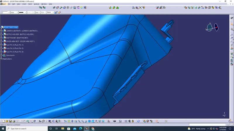
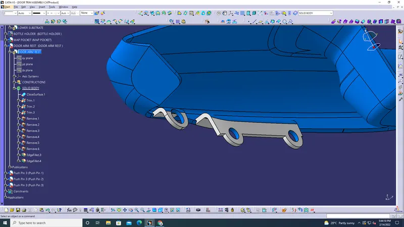
HEAT STAKES
Heat Staking is a pulsed - heat process to join two or more parts out of which one at least is made of plastic . The process is to deform the plastic material using heat and force at a set process time . The bond is made by partially de - forming the plastic part in order to fix the other . Heat Staking makes it easy to bond metal to plastic and is commonly used in high volume / low cost applications such as automotive , IT and consumer appliances
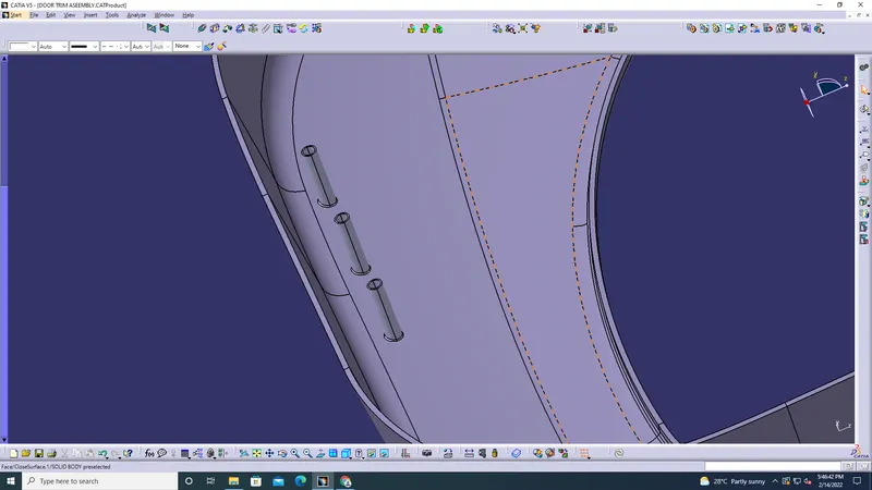
DOG HOUSE
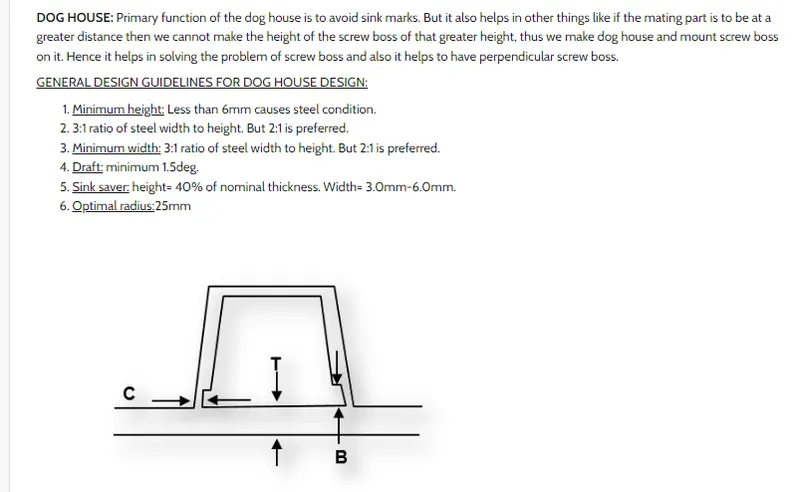
Dog house is an engineering feature used in plastic trim design . Dog houses are used as supporting features . Sometimes other engineering features like snaps ; locators etc. are mounted on them to increase their strength . Dog houses are subjected to draft analysis to prevent breakage of the component during ejection from mould cavity . Dog house and other engineering components are built on a B - surface . Dog House Design : Dog houses are used as supporting feature.Dog houses are subjected to draft analysis to prevent breakage of the component during ejection from mould cavity . Dog house and other engineering components are built on a B - surface .coaring is done on the legs of the dog house to avoid flash and improper filling of plastic while injection moulding process , It must be done by following the OEM design guidelines .
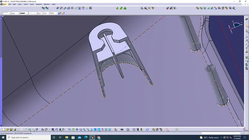
DESIGN RULES FOR DOG HOUSE
4 WAY LOCATORS
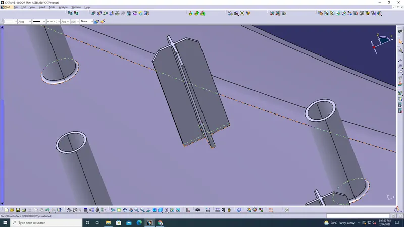
These are the locators which arrest the 4 degrees of freedom by four ribs junctioning together .
RIBS
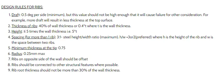
Ribs are thin , wall - like features typically designed into the geometry of a part to add internal support to walls or other features like bosses . Ribs provide a means to economical stiffness and strength in molded parts without increasing overall wall thickness . They also facilitate : Locating & arresting components of an assembly . Providing alignment in mating parts . Acting as stops or guides for mechanisms
DESIGN RULES FOR RIBS
draft analysis
Draft analysis is done on a part to determine weather the part designed must clear the ejection process smooth and perfectly without creating flaws such as
- Flow Lines.
- Sink Marks.
- Vacuum Voids.
- Surface Delamination
- Burn Marks , etc ...
procedure
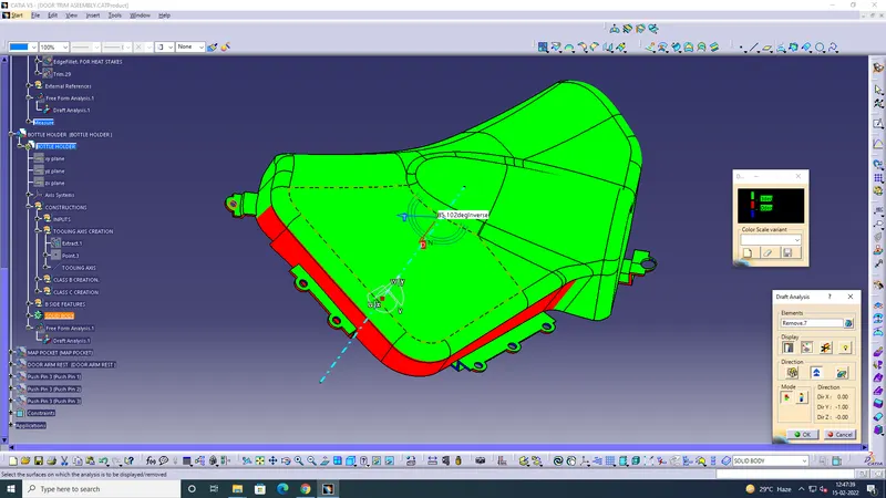
For making the draft analysis , insert the featuerd draft analysis tool , then place the compass in the created tooling axis to define the new current draft direction , then lock the draft direction by lock tool , then use the analysis under running point tool to measure the draft in the paticular position by moving the cursor along the fan cover , and set the angle in the colour scale varient as 3 degress . if the colour of the fan cover transforms into green colour , then the component is perfectely drafted to get manufactuered properly ,
Draft analysis for map pocket
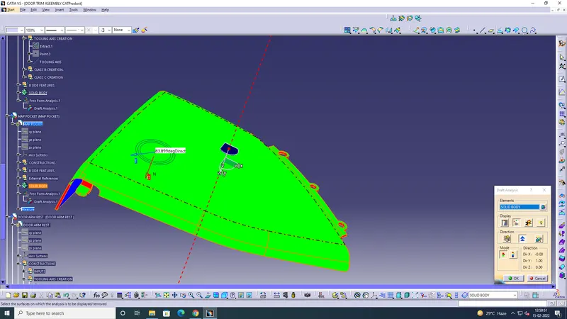
Draft analysis for lower substrate
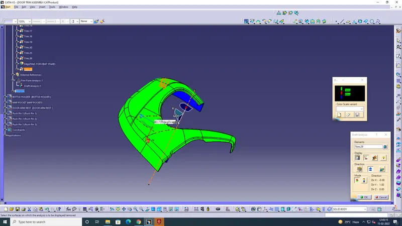
Draft analysis for door arm rest
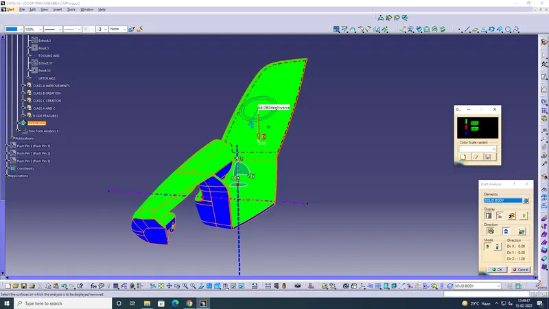
Draft analysis for bottle holder