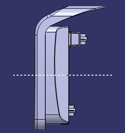
Week 9 - Attachment Feature Creation - Challenge 2
REPORT-------
Tooling axis creation
Main Tooling Axis creation
1. Brought out the Center Point of the surface from the base extract
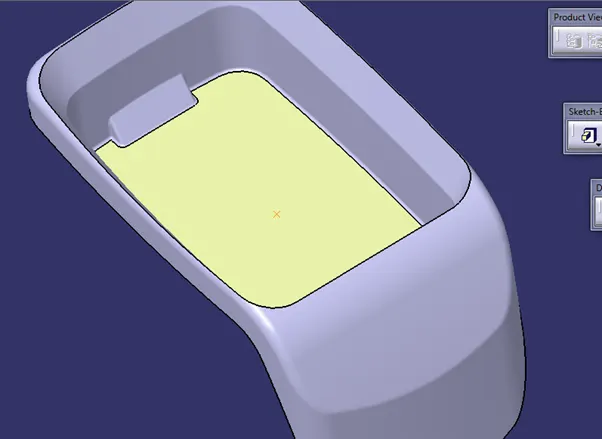
2. Axis system located at the point and intersection is drawn between the Plane and the A-Surface
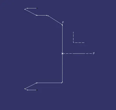
3. The A Surface intersect seems to be at a 0 degree angle with the faces with has to be in actual at an angle. But as be cannot make changes in the A surface we therefore have to request the A surface maker to add some draft to the faces.
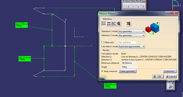
4. Therefore Tooling axis is created taking a normal line to the base Extract.
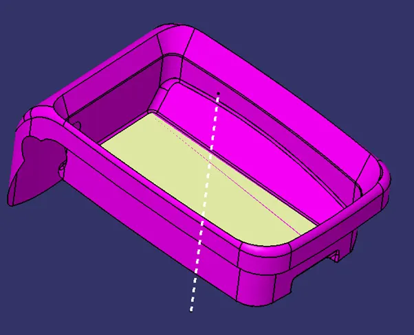
Side Tooling Axis creation
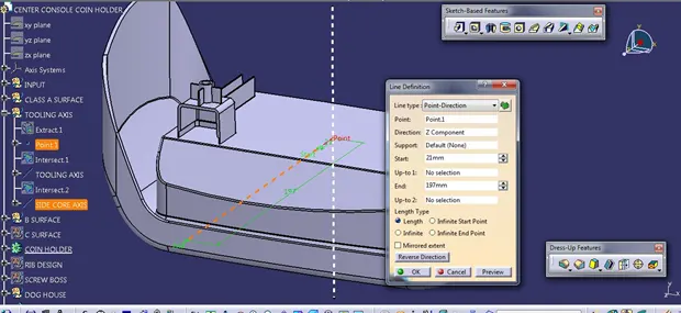
Side Tooling axis is created along the Z-axis direction with reference to the point as highlighted.
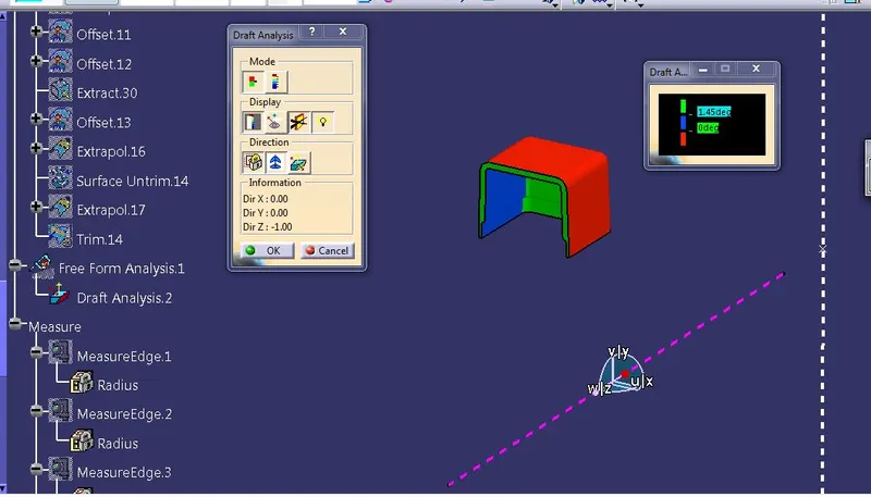
Draft analysis report of Center Console Coin Holder-
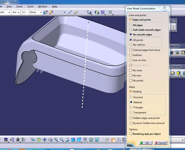
1. The component was changed to view in material mode in order to perform draft Analysis.
2. The draft analysis tool bar was initiated and the compass was mounted on the tooling axis positioning w along the mould opening and closing direction
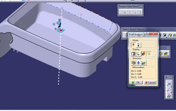
3. The draft analysis result show less then 0 degrees angles that have to be cleARED for the A surface. As the A surface itself has less then 0 degrees angles.
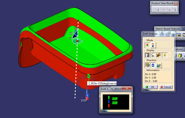
Draft analysis report of Screw Boss along main tooling-
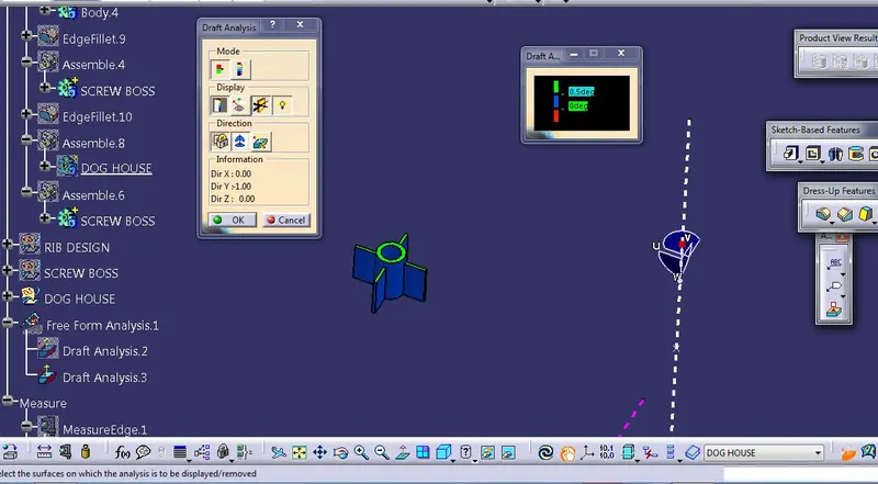
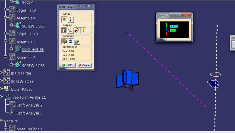
Draft analysis report of DOG House along main tooling-
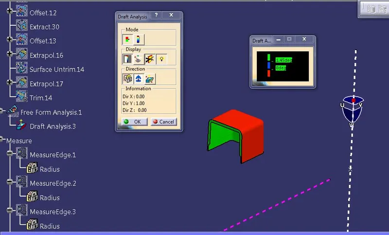
Draft analysis report of DOG House along Side core Axis-
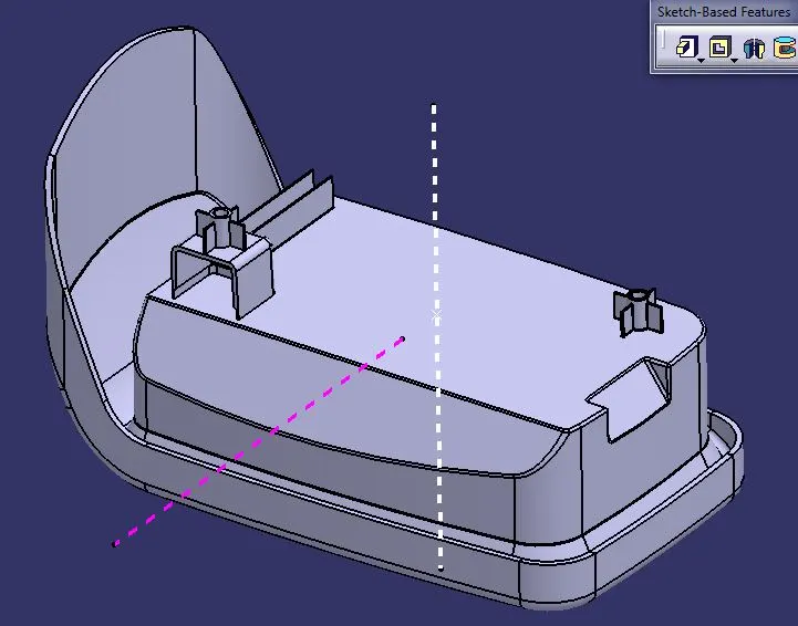
Screenshots of the completed design in various orientations (Isometric, Front, Side, and Top View)
Isometric View-
Front View-
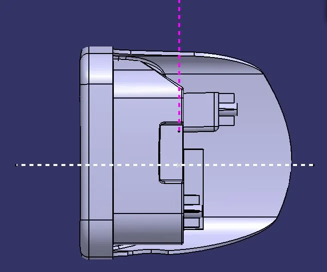
Side View-
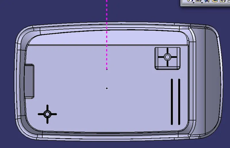
Top View-