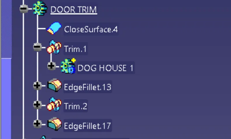
Week 9 - Attachment Feature Creation - Challenge 2
AIM:
- To Create theDoor Trim Component from the given Class-A surface.
- To Create the Tooling axis for the given Class-A Surface meeting the requirements of the draft angle.
- To perform the Draft analysis on the model.
- To Create the B Side Feature in the component by following the design rules.
PROCEDURE:-
1)DRAFT ANALYSIS OF CLASS A:-
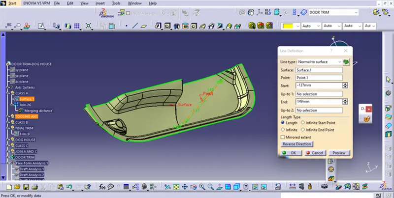
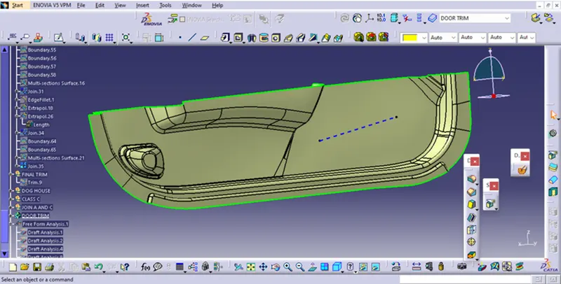
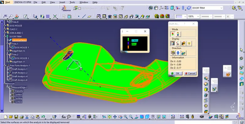
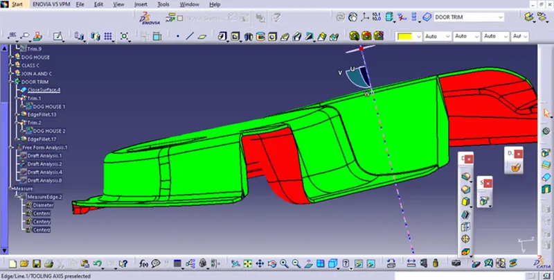
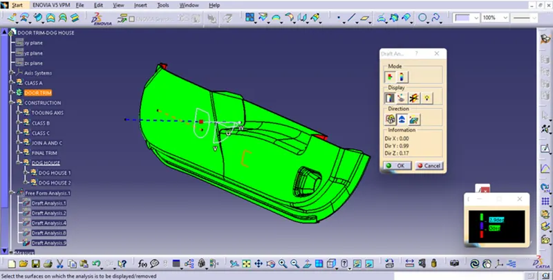
Tooling axis is created using point on surface and line is normal to surface.Using that tooling we do the draft analysisof class A to check its feasibility or formability.
- Before going to draft analysis go to customized view parameter >under mesh >check material and then click ok.
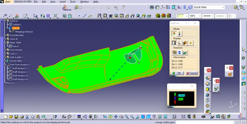
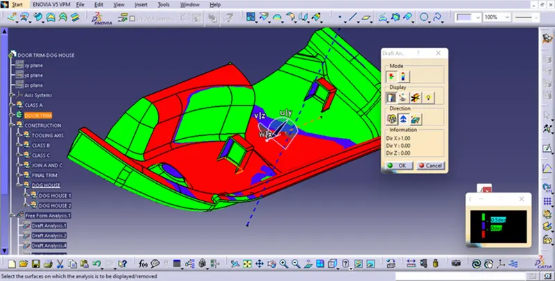
- Now for draft analyses go to insert » analysis » feature draft analysis.
- Use the compasss to define the draft direction.
- In the colour scale change the draft angle to 3 degree.
- The component changes to green in indication of passing draft angle.
- Use running point to check the angle on the component.
2) CREATING CLASS B SURFACE:-
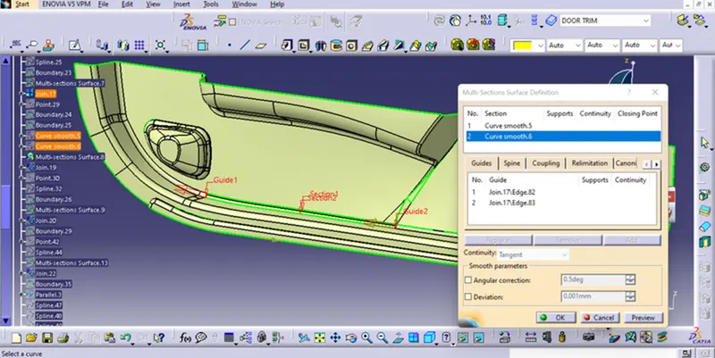
- Extract the surfaces from the class A using multiple extract and untrim them.
- Use Extrapolate to make sure that all the untrims are properly intersected to trim and offset the surfaces 2.5 mm to create the thickness.
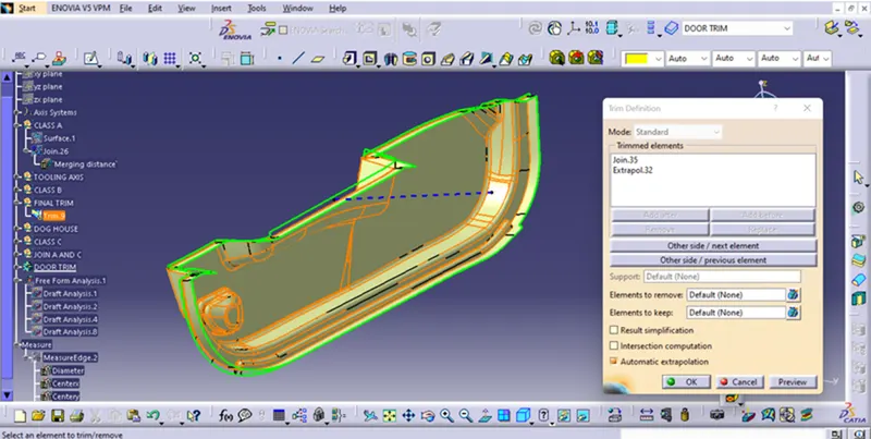
- Trim the extra surfaces using trim command.
- Insert them into new geometrical set and name it with respective part names.
Apply fillets to the model after creating the entire surface.
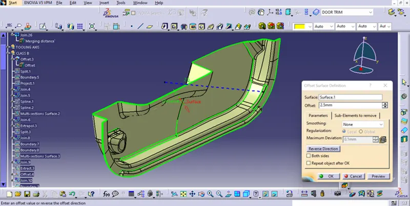
- The patches which are not offseted these are filled using commands like boundary,multi section surface and sweep.
3)CREATING CLASS C SURFACE:-
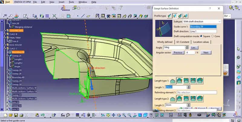
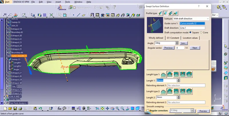
- Extract the boundary from the class A surface using boundary command.
- Using disassemble tool to divide the boundary as the boundary contains domains.
- Use sweep command > choose profile type line > subtype as with draft direction > choose guide curve and draft direction > draft angle as 3 degree > preview.
- The class A and Class B surafces are joined:-
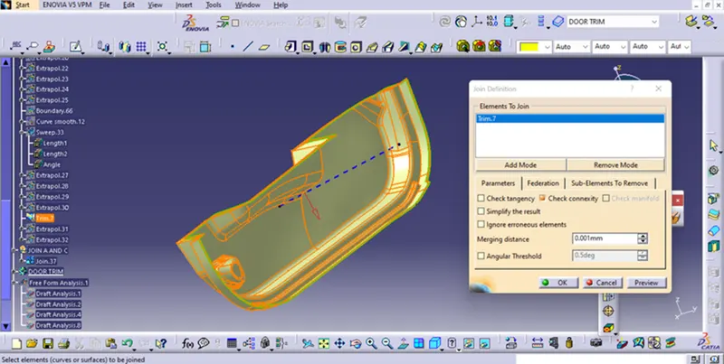
FINAL TRIM:-
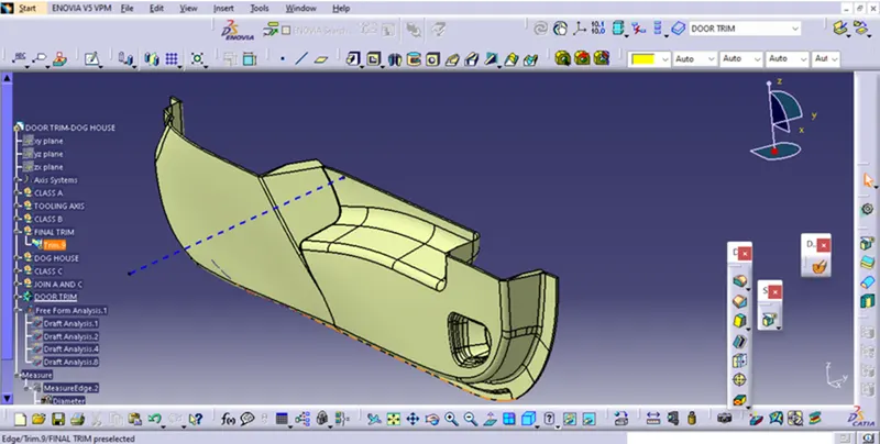
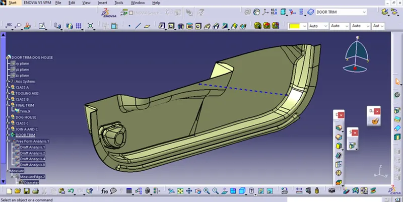
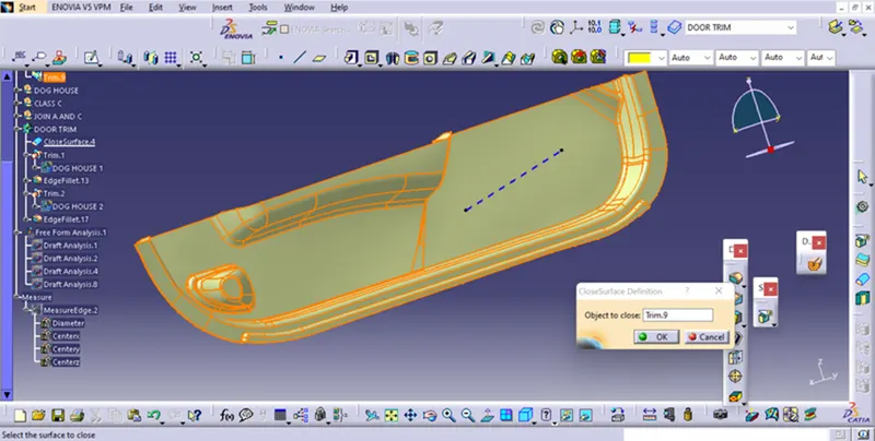
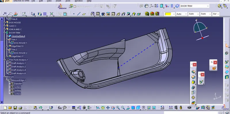
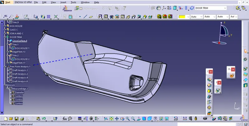
CLOSE SURFACE:-
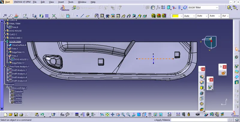
DRAFT ANALYSIS OF SOLID :
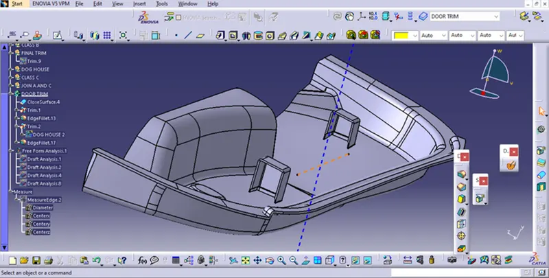
4) B SIDE FEATURES (DOG HOUSE) CREATION:-
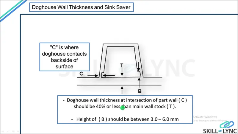
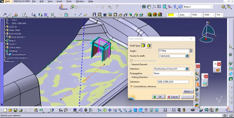
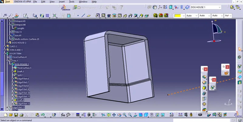
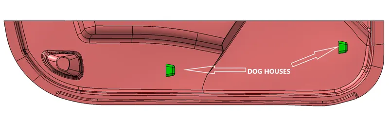
The dog house is an engineering feature used in the plastic trim design. Dog houses are used as a supporting feature. Sometimes other engineering features like snaps; locators, etc. are mounded on them to increase their strength.The doghouse is created by following the design rules.The nominal wall thickness guide range is from 0.75 mm to 3 mm for reinforced materials and 0.5 mm to 5 mm for unreinforced materials.Related Courses
WALL THICKNESS (W) = 0.70 (NOMINAL THICKNESS OF PLASTIC MATERIAL)
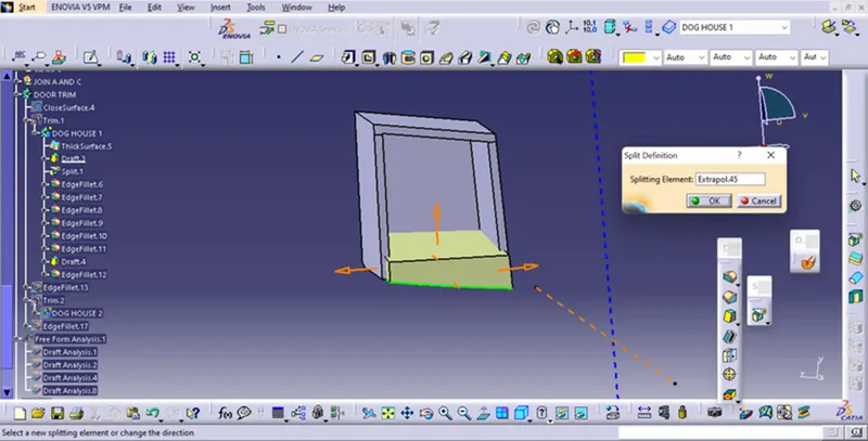
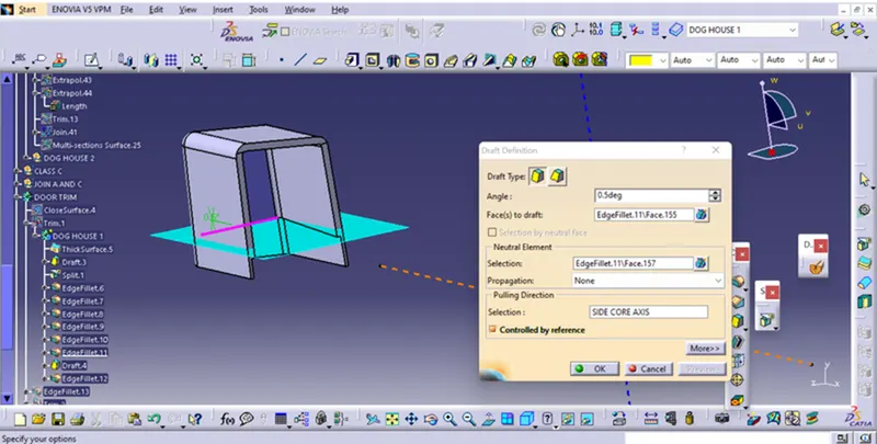
This process is usually done by Thicken surface command.The fillets and the draft are given as per the design rules.An important thing while designing a doghouse is to maintain 40% less thickness than the wall thickness (T) at the area of the intersection to avoid sink marks. So, a C shape is formed at the intersection.This can be made using the split command to remove the solid at the intersection.
SIDE CORE:-
To create dog house side core is used because its not its side feature and can't be manufactured by the main core and cavity only.
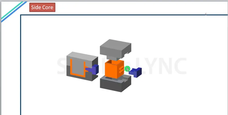
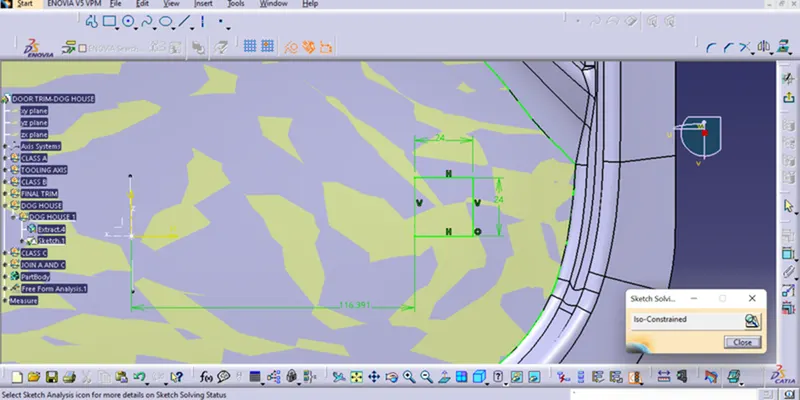
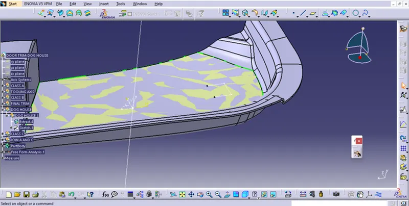
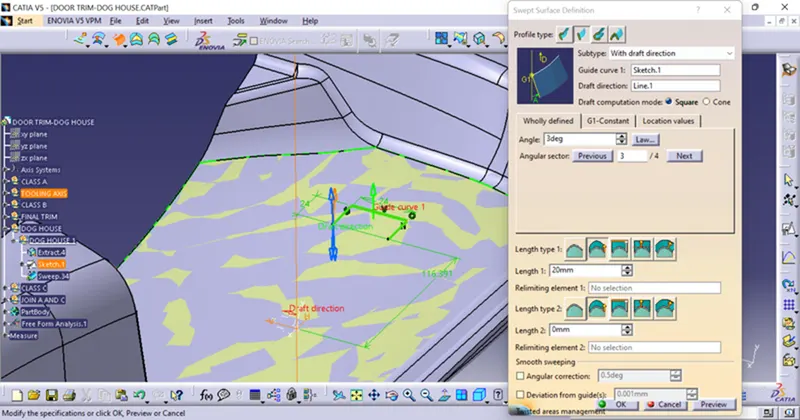
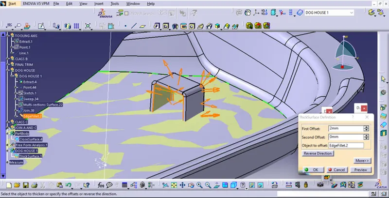
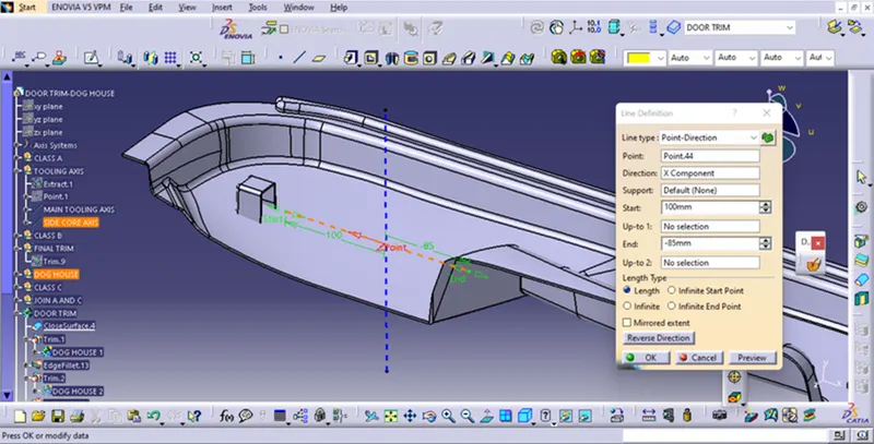
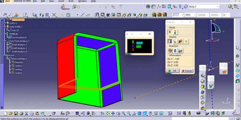
SIDE CORE AXIS:-The side core axis is created to normal to the X axis. The dog house inner walls will be cleared using the side core axis
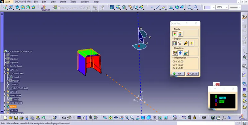
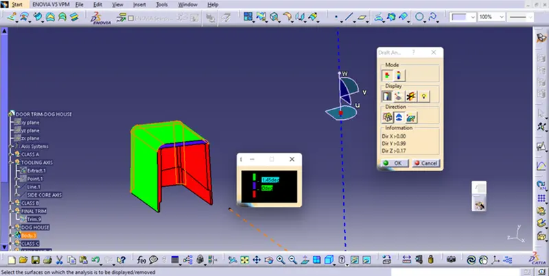
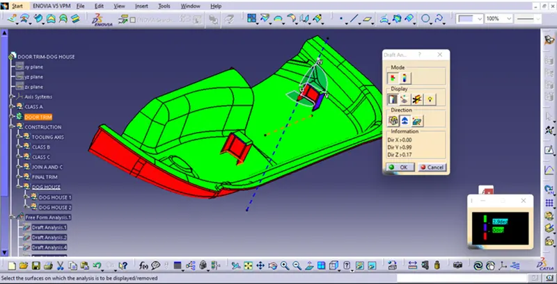
DRAFT ANALYSIS OF DOG HOUSE FROM DIFFERENT DRAFT ANGLE:-
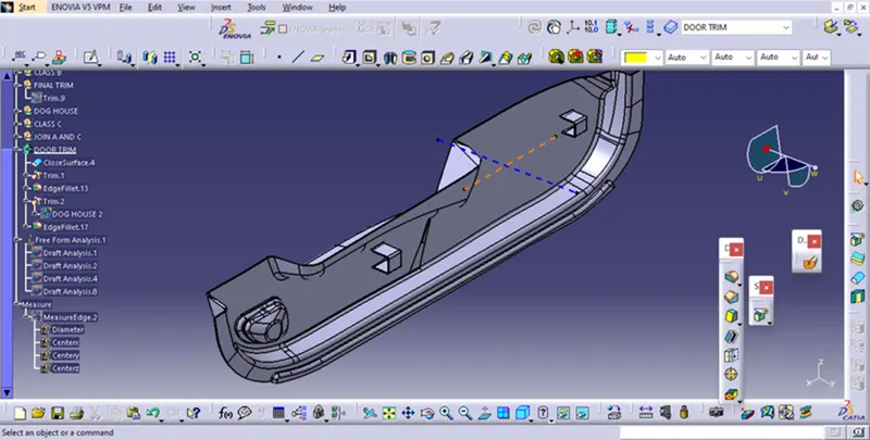
5)FINAL PART AND DRAFT ANALYSIS :-
FEATURE TREE:-