Week 9 - Attachment Feature Creation - Challenge 2
the tooling axis is selected in y direction.that is line noemal to zx olane.no bisecting method is choosed.from y axis itself maximum view is possible.
draft analysis in surface a is shown in fig.
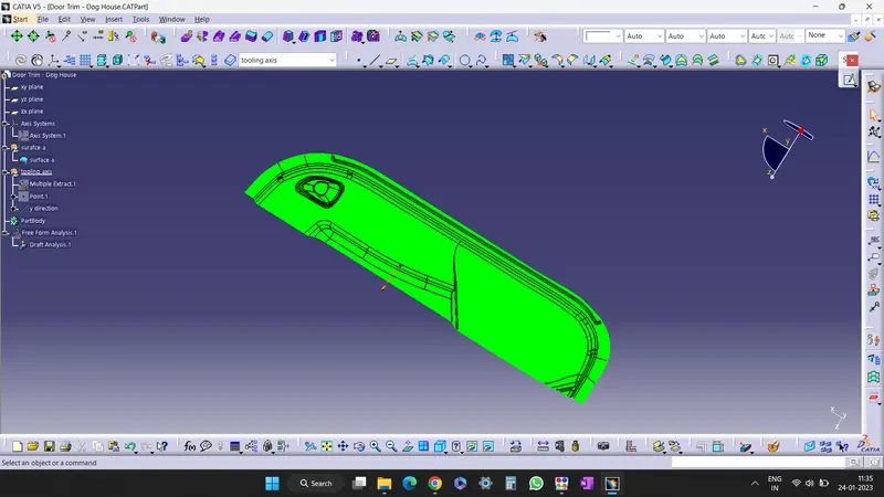
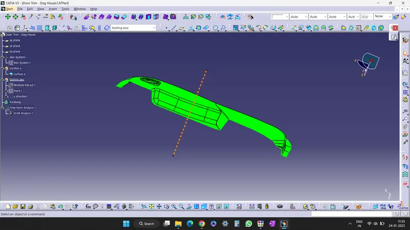
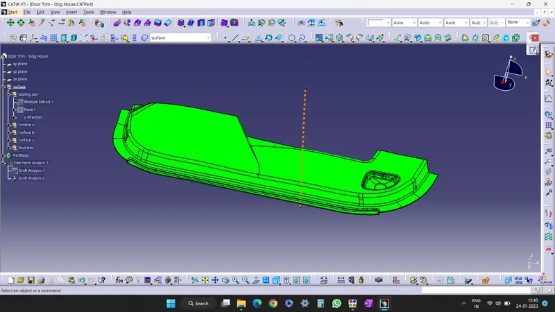
there is some region in surface a where angle is below 0 degree in cavity region.but overall surface regions is more than 3 degree.
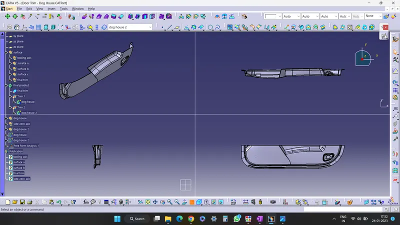
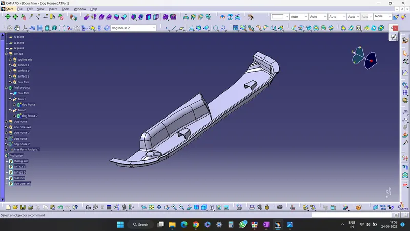
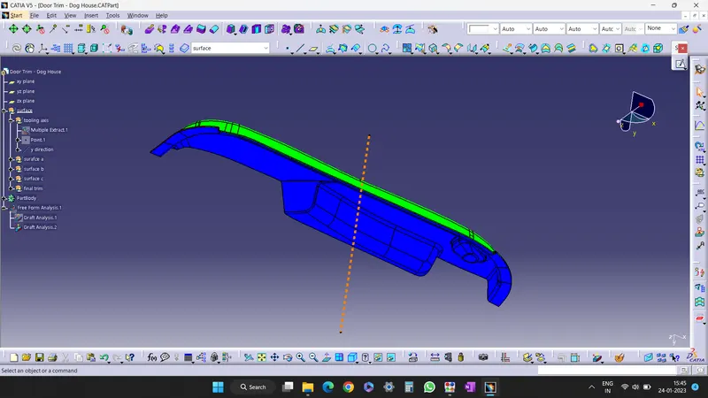
the draft analysis of finished product is shown below.in some areas
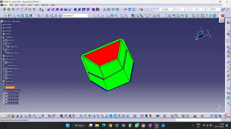
the draft analysis of dog house 1 is shown below.the draft analysis is done with side core axis since we cannot mould this part from previous tooling axis.the side core axis in direction of x axis or we can say line normal to zy plane.
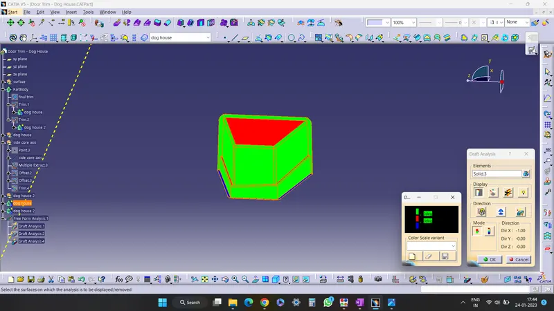
the draft analysis of dog house 2 is shown below.