Week 9 - Attachment Feature Creation - Challenge 1
CONSTRUCTION and DRAFT ANALYSIS of COIN HOLDER
Draft analysis technique is used to analyze whether our part model created in CAD is manufacturable or not. The part should get easily removed from the mould or die. No part can be ejected from the tool if it is having straight 90 degree angle from its base surface. A small draft angle is provided to each and every area of the component and we are providing a direction in which components should eject in order to easily remove the component from the tool.
Draft Angle is the amount of taper given to the molded parts perpendicular to the parting line. As the plastic cools it shrinks and sticks to the mould surface and therefore need draft angle while ejecting, and to avoid damage. Normal draft angle is 3 degree. Increasing draft value will increase manufacturing cost.
TOOLING AXIS
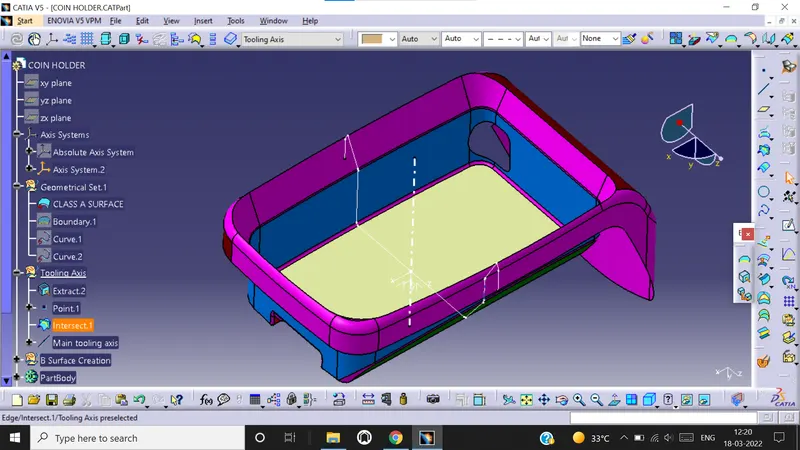
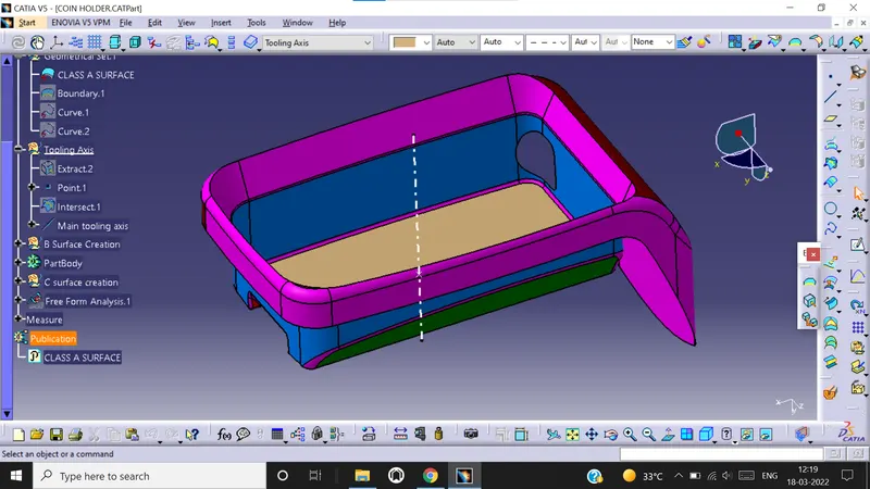
In order to perform analysis, we need to create tooling axis and in order to do that we need to check class A surface first. We need to check whether all the surfaces are closed or not using boundary option. Once inspection is complete, we need to create separate geometrical set for tooling axis. We need to choose the axis in such a way that all the pockets, holes, sections etc. should get covered. For example, once inspection is completed, we concluded that Z axis is the tooling axis. Now we first extract the base surface from class A surface.We than create a reference point at the centre of the surface. Now insert an axis system at that point. Create a line at that point. This line is our MAIN TOOLING AXIS.
DRAFT ANALYSIS
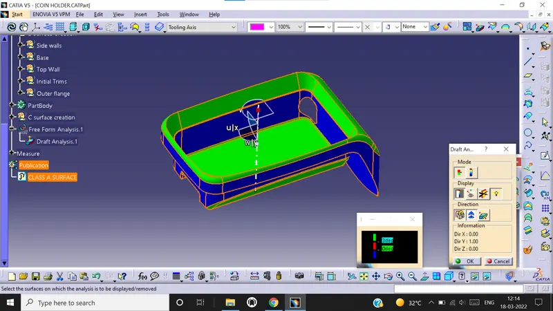
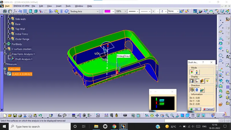
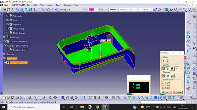
Now we need to check whether material mode of class A surface is in customize view parameters. Now go to Insert – Analysis - Feature draft analysis. Select the compass mode and drag the compass to the tooling axis of class A surface . Now select the surface to activate the surface and lock it using lock button. You can also do analysis during running point and move mouse all over the surface to check degree and draft angle. You can do analysis on full scale mode or quick scale mode. The color change shows change in draft angle.
RIB design
Rib is an engineering feature on the class B surface which provides strength and stiffness to the plastic molded parts without increasing their thickness.
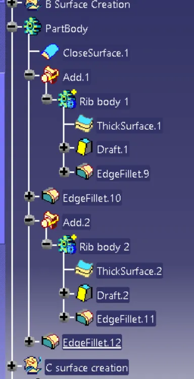
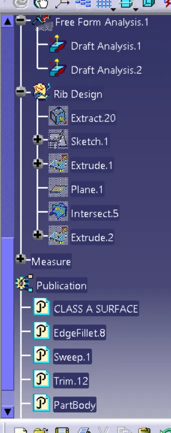
We extract the base surface of the coin holder and select it to create the sketch.
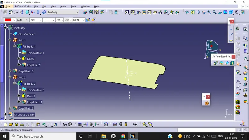
Create two lines in the sketch and maintain required spacing. Spacing= 2*t = 2*2.5 = 5mm.
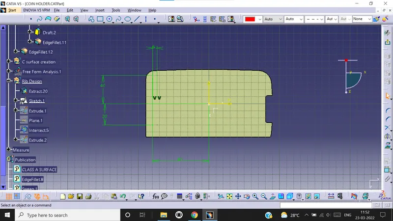
Extrude the sketch following the design rule, Height = 5*t(thickness of the body)= 5*2.5 = 12.5mm. Also extrude it 1mm below so that it intersects the part body.
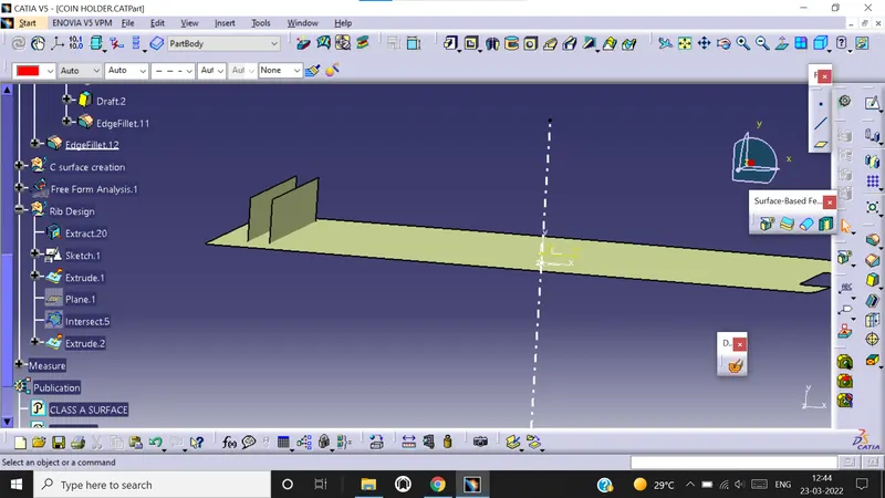
Now go to part work bench and use thicken option to thicken the extrude. Thickness= 0.5*t
Thickness = 0.5*2.5 = 1.25mm. Thicken the extrude to 1mm on 1 side.
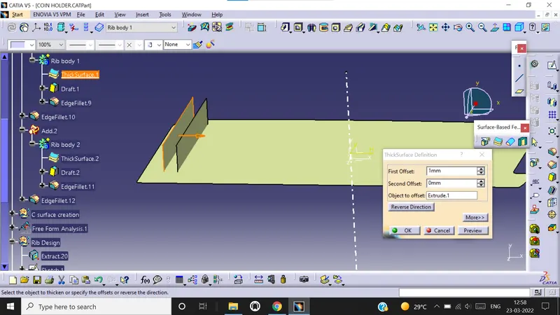
Now add the RIB to the main body using boolean operation. Provide draft of 0.5degree to all the surfaces of the rib. Provide fillet radius of 0.25mm to all the edges of rib.
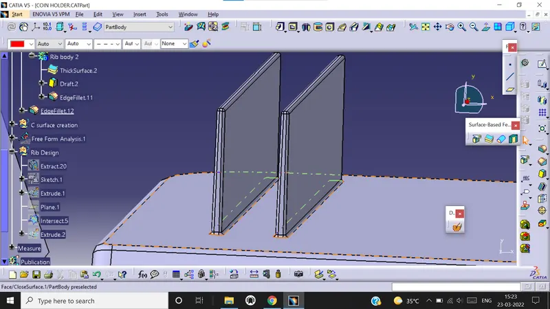
Now take the intersection.
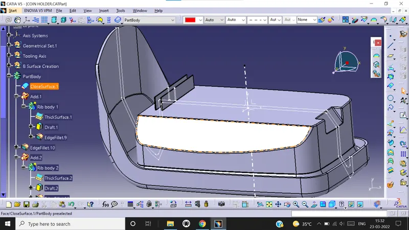
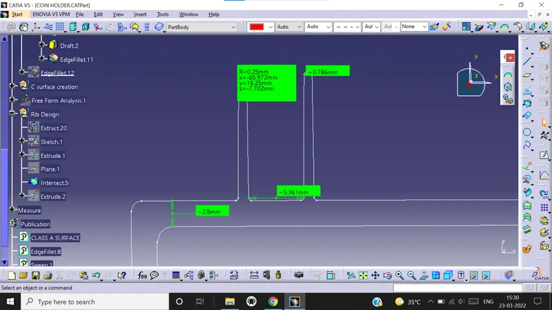
Now we do draft analysis to rib side . We change the degree range from 0 to 0.45 degree, since our draft angle is 0.5 degree.
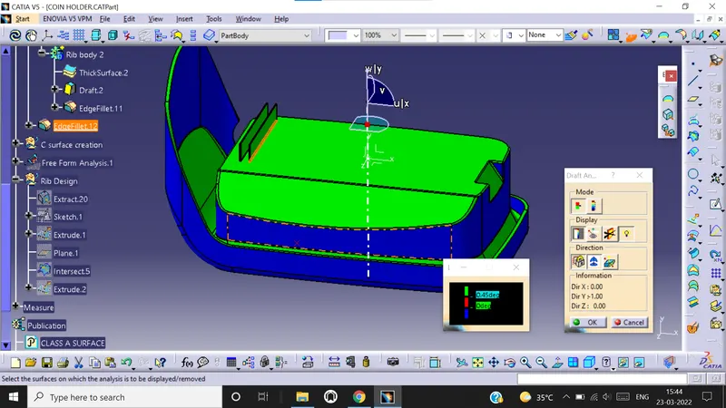
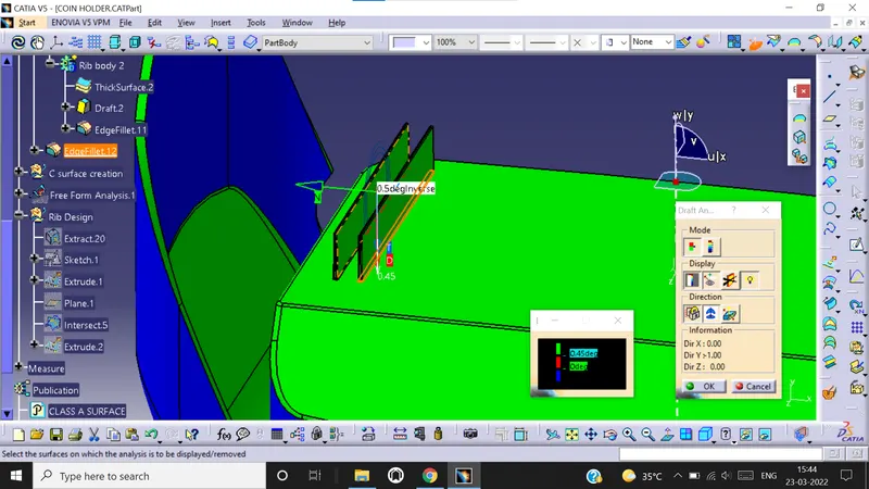
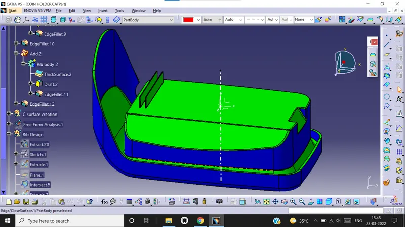
After draft analysis you can see that the surface also has negative draft. This is because the side walls of the surface is either 0 degree or exactly 90 degree to the base surface, because of which during manufacturing the side walls of the component might get damaged during part ejection. The solution is to recommend the class A surface designer to give a minimum draft angle of 3 degree to all the walls.