Photo Realistic Rendering
AMERICAN CHOPPER BIKE
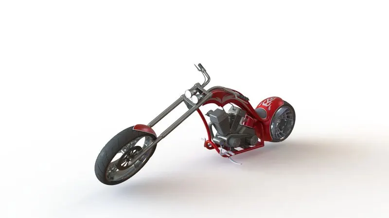
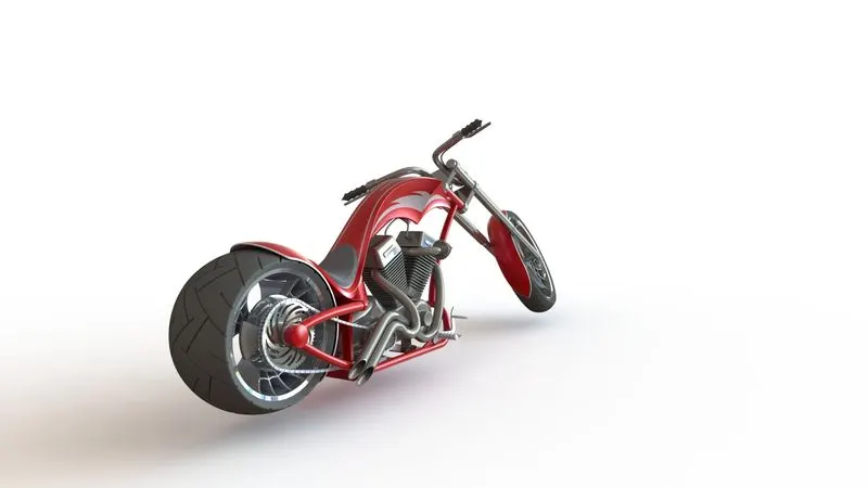
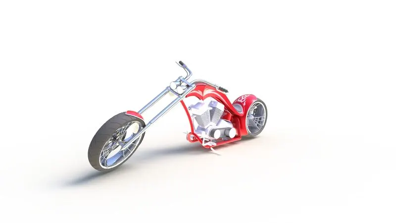
OBJECTIVE: The objective of this project is to create different parts of american chopper bike using solidworks and assemble the parts of the bike and do rendering of the bike using photoview360 using solidworks.
INTRODUCTION: Here part modelling is used to create the parts of chopper bike and then later assembled togather to form the bike.
Parts used for chopper bike are as listed below:
1) Chassis
2) Engine
3) Front Fork
4) Front Wheel
5) Front Fender
6) Rear Wheel
7) Rear Fender
8) Fuel Tank
9) Pedal
10) Transmission Belt
11) Chain Link
12) Oil Tank
13) Kick Stand
1) Chassis: Features used to create chassis are as listed below;
# Blueprint of chopper bike
# sketch (curves)
# sweep
# Boss extrude
# cut extrude
# fillets, chamfers and dome
# reference planes
# revolve
# split
# mirror
# combine
# appearence
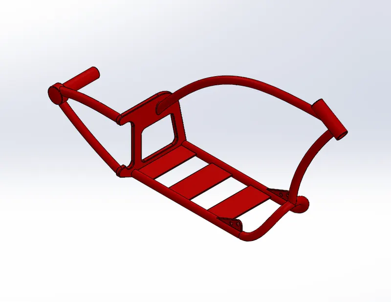
2) Engine: Features used to create engine are as listed below:
# Blueprint of chopper bike
# sketch (curves)
# sweep
# Boss extrude
# cut extrude
# fillets, chamfers and dome
# reference planes
# revolve
# split
# mirror
# circular pattern
# linear pattern
# composite curve
# project curve
# appearence
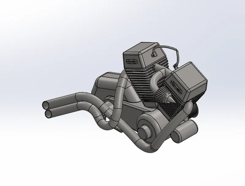
3) Front Fork: Feature used to create front fork are as listed below;
# sketch (curves)
# sweep
# Boss extrude
# fillets and dome
# reference planes
# revolve
# split
# mirror
# Project curve
# combine
# appearence
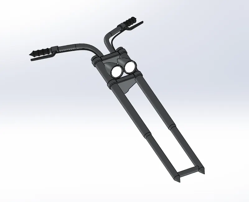
4) Front Wheel: Features used to create front wheel are as listed below;
# sketch (curves)
# Boss extrude
# cut extrude
# fillets, chamfers and dome
# reference planes
# revolve
# revolve cut
# circular pattern
# linear pattern
# combine
# appearence
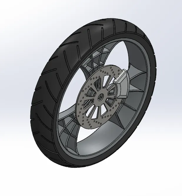
5) Rear Wheel: Features used to create Rear wheel are as listed below;
# sketch (curves)
# Boss extrude
# cut extrude
# fillets, chamfers and dome
# reference planes
# revolve
# revolve cut
# circular pattern
# linear pattern
# combine
# appearence
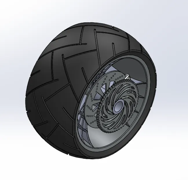
6) Front fender: Features used to create front fender are as listed below;
# sketch (curves)
# fillets
# reference axis
# revolve
# split
# appearence
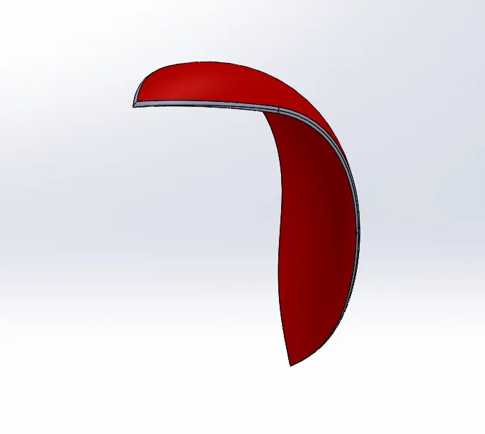
7) Rear fender: Features used to create rear fender are as listed below;
# sketch (curves)
# fillets
# reference axis
# revolve
# split
# appearence
# Decals
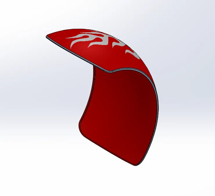
8) Fuel Tank: Features used to create fuel tank are as llisted below;
# sketch (curves)
# reference plane
# fillets
# blueprint of chopper bike
# sweep surface
# surface lost
#surface knit
# split
# mirror
# cut surface
# appearence
# Decals
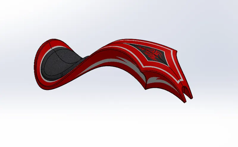
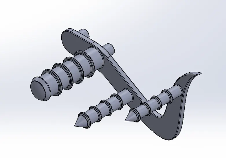
9) Pedal: Features used to create pedsal are as listed below;
# sketch (curves)
# Boss extrude
# fillets,chamfer and dome
# reference axis
# revolve
# linear pattern
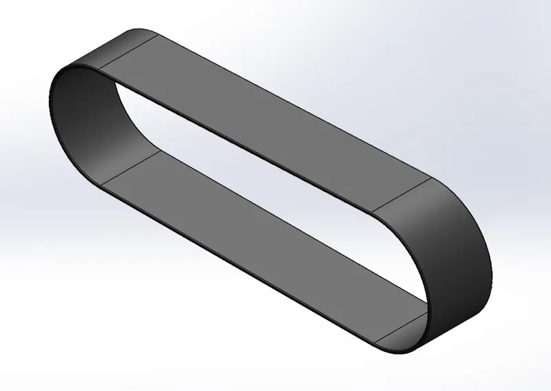
10) Transmission Belt: Features used to create transmission belt are as follows;
# sketch
# Boss extrude
# cut extrude
# filets
# appearence
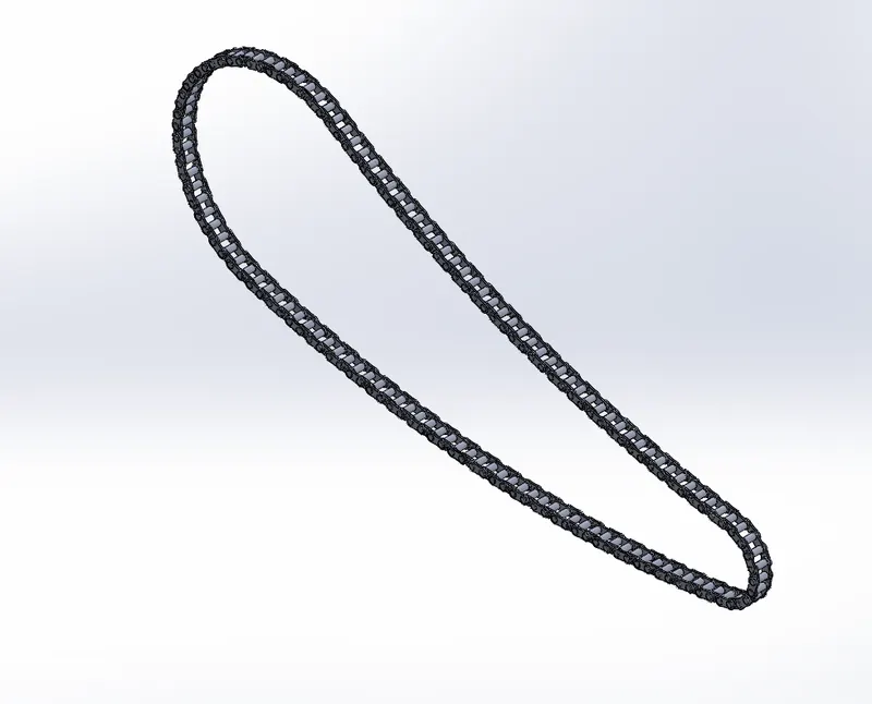
11) Chain link: Features used to create chain link are as follows;
# sketch
# boss extrude
# fillet
# curve pattern
# mirror
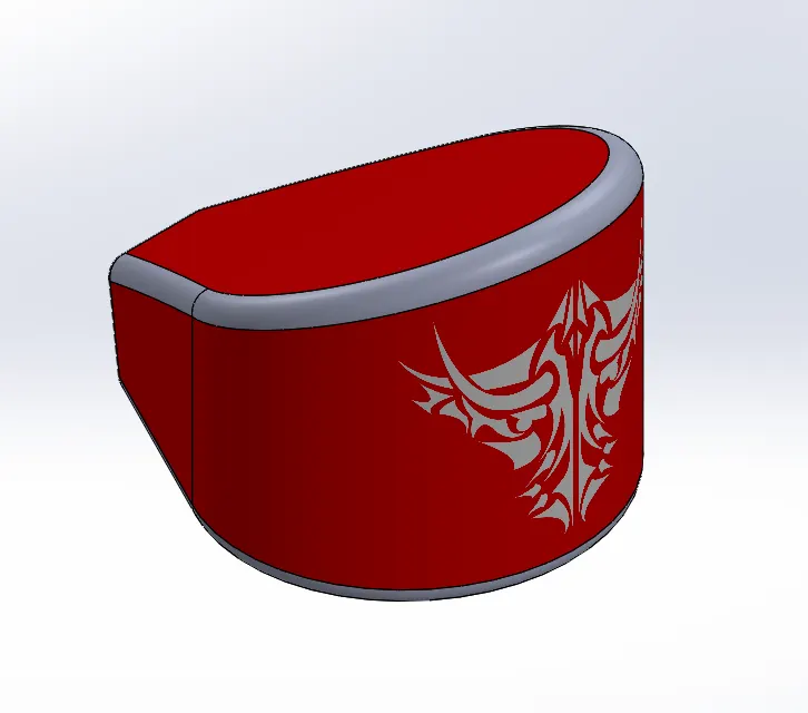
12) Oil Tank: Features used to create oil tank are as listed below;
# sketch
# boss extrude
# combine
# fillet
# shell
# appearence
# decals
13) Kickstand: Features used to create kickstand are as listed below;
# sketch(curves)
# Boss extrude
# loft
# dome and fillet
# reference plane
# cut extrude
# split
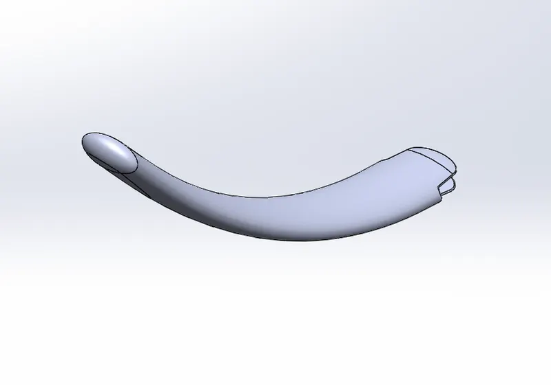
ASSEMBLY OF CHOPPER BIKE
1)Here all the parts of chopper bike are first inserted into assembly window
2) Then the parts are brought into assembly environment and fixed using MATE option (coincidence, parallel, concentricity, width, distance, angle etc...)
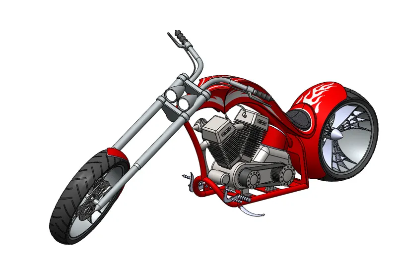
RENDERING OF CHOPPER BIKE
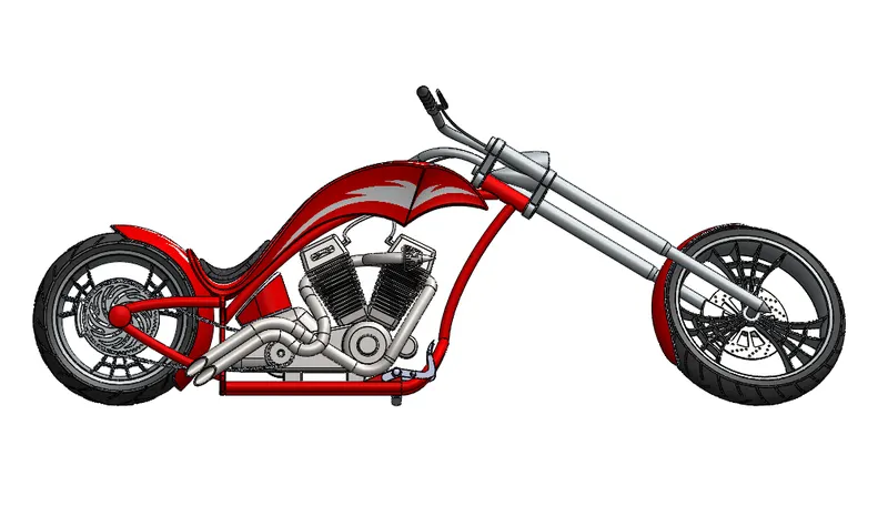
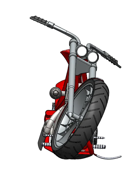
1)Rendering means creating photorealistic environment of the given model.
2) In this project rendering is done using photoview360 .
CONCLUSION
1) The parts of the chopper bike are modelled and assembled in assembly section.
2) Then the model is rendered using photoview360.