Week 9 - Attachment Feature Creation - Challenge 1
Rib Design for the B side:
- In generative Shape Design Workbench, Extract the base from B Surface and Create a Plane on it as shown

Figure25: Extract of base of B surface and Plane Creation on it.
- Create a Sketch on the Plane for the rib as shown in Figure 26
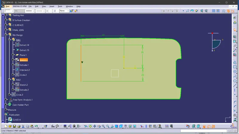
Figure26: Sketch for Rib.
- Extrude the sketch to the value of 12.5mm following the Design rule of Height of Rib <= 5 x thickness of base = (5 x 2.5 = 12.5mm).
- Also extrude it 1 mm below the surface so that it intersects the base.
- Extrude shown in Figure 27.
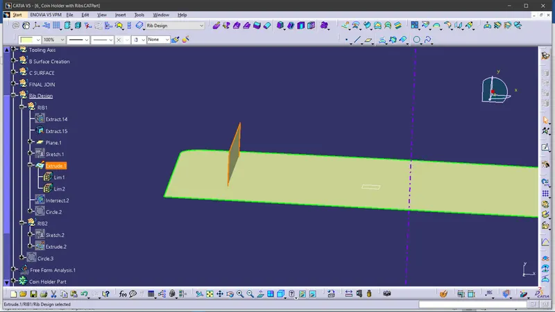
Figure27: Extrude for Rib.
- Switch to part design workbench and thicken the rib to a base thickness value as per design rule.
- Thickness should be 0.5 times the base wall thickness (i.e., 0.5 x 2.5 = 1.25mm).
- Thicken it 0.75mm on each side.
- Thicken shown in Figure 28.
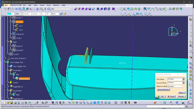
Figure28: Thicken For 1st Rib.
- Assemble the Rib to the main Coin Holder Part.
- Use draft of 0.5º on all the walls which are along the Tooling Direction.
- Also give fillets of 0.25mm to all the edges.
- Do similar operations for the 2nd Rib by keeping in mind the spacing between the ribs to follow the design rules which is height to spacing ratio to be 3:1 or 2:1.
- The Rib shown in Figure 29 shows the above operations.
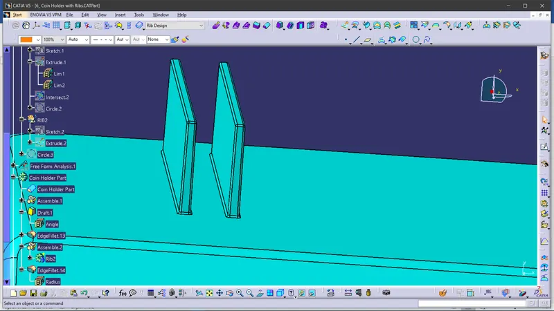
Figure29:Assembly of Rib1,Draft and Fillets on it.
- Take a section of the Final Part with the XY plane to check the application of Design rules of the Ribs are satisfied.
- The Figure 30 shows the considerations being satisfied according to the Rib Design Rules.
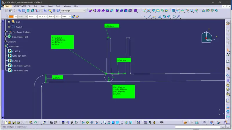
Figure30:Design Considerations for Ribs shown with measure on Intersect.
Step 9: Perform Draft Analysis on the Final Closed Surface:
- Change View Mode Customization to Material mode
- Go to INSERT à ANALYSIS à FEATURE DRAFT ANALYSIS and move the compass to the Tooling Axis. Change the range to 0.45º. Apply the settings as Shown in Figure 31
- The Final Draft analysis passes on the Ribs but does not pass on the Side walls since the class A contained Parallel walls and walls without draft. This component will be costly to manufacture or may even fail causing loss in Time and Cost.
- The design for the Walls should be reconsidered by the Class A design team
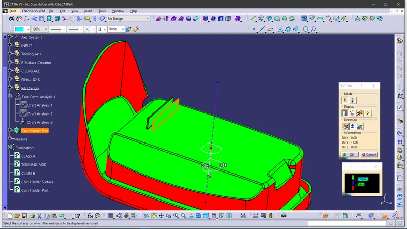
Figure31: Draft Analysis on Coin Holder.
- Other view of the Draft Analysis is shown below in Figure 32.
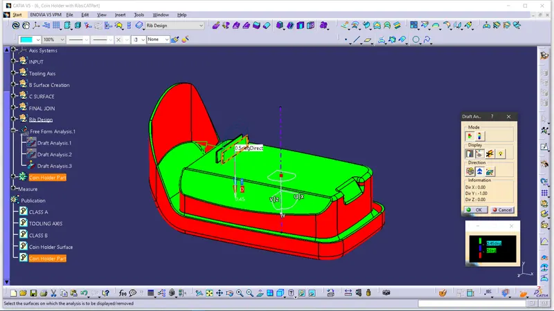
Figure32: Draft Analysis on Closed Surface of Coin Holder.
Conclusion:
The Design of Automotive Plastic Component – Center Console Coin Holder from Class A is completed using concepts of Draft angle, Draft Analysis for Class A and Final enclosed surface, Tooling Axis creation and implementation, Class B and Class C creation and conversion to a solid part.