Week 9:- 2D Detailing Challenge
WHAT ARE DRAWING TEMPLATES?
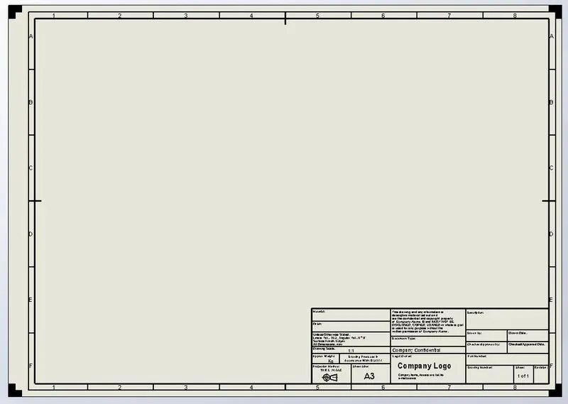
Drawing templates are the basic drawing standards for a specific customer. Drawing templates are used to detail the different parts and features of the unit. Templates are used to denote various details and features including tolerances, measures, finishes, name of parts and assemblies etc.
Preparing the template at the start of the project can save time and the same can be used to template future projects. They also give important information like the angle of projection, scaling, units etc.
The templates have spaces for Title block, name of the designer, supervisor, parts list and number of parts.
WHAT DO YOU UNDERSTAND BY ANGLE OF PROJECTION?
In technical drawing and computer graphics, a multiview projection is a technique of illustration by which a standardized series of orthographic two-dimensional pictures are constructed to represent the form of a three-dimensional object. Up to six pictures of an object are produced (called primary views), with each projection plane parallel to one of the coordinate axes of the object. The views are positioned relative to each other according to either of two schemes: first-angle or third-angle projection. In each, the appearances of views may be thought of as being projected onto planes that form a six-sided box around the object. Although six different sides can be drawn, usually three views of a drawing give enough information to make a three-dimensional object. These views are known as front view, top view and end view. Other names for these views include plan, elevation and section.
The terms orthographic projection and orthogonal projection are sometimes reserved specifically for multiview. However, orthographic and orthogonal more correctly refer to the right angle formed between the projection rays and the projection plane, versus the angle formed between the subject of the drawing and the projection plane.
First and third angle projection are nothing but ways of describing what an object looks like from different directions. This is called orthographic projection and orthographic is nothing but engineering drawings or plan views.
First angle of projection:
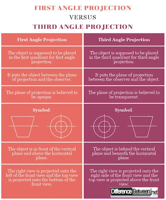
This is one of the most common methods used to obtain engineering drawings, mostly for orthographic projections. Orthographic projection is a graphical method used to represent three-dimensional structures or objects into different perspective projection images called views. The orthographic view typically consists of the top view, front view, and the side view. First angle projection is one of the methods used for orthographic projection drawings and is approved internationally except the United States. In this projection method, the object is placed in the first quadrant and is positioned in front of the vertical plane and above the horizontal plane.
Third angle of projection:
This is another perspective projection method used to represent three-dimensional objects using a series of two-dimensional views. In third angle projection, the 3D object to be projected is placed in the third quadrant and is positioned behind the vertical plane and below the horizontal plane. Unlike in first angle projection where the plane of projection is supposedly opaque, the planes are transparent in third angle projection. This projection method is mainly used in the United States and Japan stipulates the use of third angle projection schema for industrial designs for product fabrication.
WHAT IS FIRST ANGLE AND THIRD ANGLE PROJECTION? AND WHY CAN'T WE USE 2ND AND 4TH ANGLE OF PROJECTION?
First and third angle projection are nothing but ways of describing what an object looks like from different directions. This is called orthographic projection and orthographic is nothing but engineering drawings or plan views.
First angle of projection:
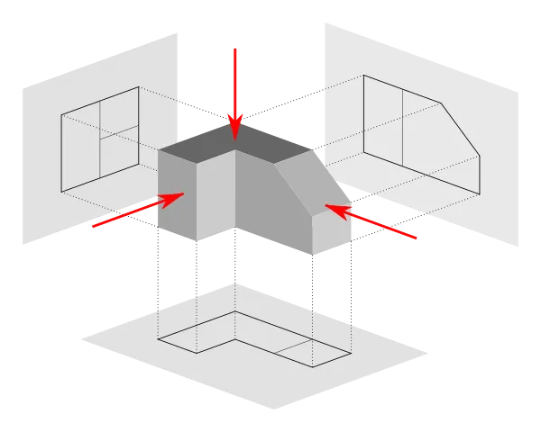
This is one of the most common methods used to obtain engineering drawings, mostly for orthographic projections. Orthographic projection is a graphical method used to represent three-dimensional structures or objects into different perspective projection images called views. The orthographic view typically consists of the top view, front view, and the side view. First angle projection is one of the methods used for orthographic projection drawings and is approved internationally except the United States. In this projection method, the object is placed in the first quadrant and is positioned in front of the vertical plane and above the horizontal plane.
Third angle of projection:
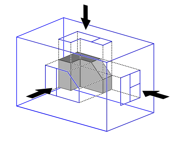
This is another perspective projection method used to represent three-dimensional objects using a series of two-dimensional views. In third angle projection, the 3D object to be projected is placed in the third quadrant and is positioned behind the vertical plane and below the horizontal plane. Unlike in first angle projection where the plane of projection is supposedly opaque, the planes are transparent in third angle projection. This projection method is mainly used in the United States and Japan stipulates the use of third angle projection schema for industrial designs for product fabrication.
In the 2nd and 4th angle projection system, the top and front views are overlaps with each other. In the 2nd angle projection system, the plane is in between object and observer. When we turn the adjacent plane by 90 degrees to see the top view, the front and top views are overlapped to each other. The same problem occurs in the 4th angle of projection. The only difference is that in 4th angle of projection the object is in between the observer and plane.
WHAT IS GD&T? WHAT ARE THE BENEFITS OF GD&tT?
Geometric Dimensioning and Tolerancing (GD&T) is a system for defining and communicating engineering tolerances. It uses a symbolic language on engineering drawings and computer-generated three-dimensional solid models that explicitly describe nominal geometry and its allowable variation. It tells the manufacturing staff and machines what degree of accuracy and precision is needed on each controlled feature of the part. GD&T is used to define the nominal (theoretically perfect) geometry of parts and assemblies, to define the allowable variation in form and possible size of individual features, and to define the allowable variation between features.
Dimensioning specifications define the nominal, as-modelled or as-intended geometry. One example is a basic dimension.
Tolerancing specifications define the allowable variation for the form and possibly the size of individual features, and the allowable variation in orientation and location between features. Two examples are linear dimensions and feature control frames using a datum reference.
There are several standards available worldwide that describe the symbols and define the rules used in GD&T. One such standard is the American Society of Mechanical Engineers (ASME) Y14.5. This article is based on that standard, but other standards, such as those from the International Organization for Standardization (ISO), may vary slightly. The Y14.5 standard has the advantage of providing a fairly complete set of standards for GD&T in one document. The ISO standards, in comparison, typically only address a single topic at a time. There are separate standards that provide the details for each of the major symbols and topics (e.g. position, flatness, profile, etc.).
Benefits of GD&T:
- Saving Money — GD&T enhances design accuracy by allowing for appropriate tolerances that maximize production. For many projects, the process provides extra or bonus tolerances, further increasing cost-effectiveness.
- Ensuring Dimensional and Tolerance Requirements — By explicitly stating all design requirements, a thorough GD&T process guarantees accurate fulfilment of all dimensional and tolerance specifications.
- Assisting Digital Design Methods — Clear, concise GD&T data is readily adaptable to digital design programs, including nearly universally used 2D and 3D CAD files.
- Offering Uniformity and Convenience — As a single, consistent language, GD&T reduces guesswork and interpretation while ensuring consistent geometries across design and manufacturing.
- Providing Accurate Communication — Today’s intricate designs demand the most accurate and reliable communication. GD&T enables designers, manufacturers, and inspectors to communicate clearly with one other, saving time and making the process more efficient.
EXPLAIN THE SYMBOLS USED IN GD&T?
Geometric Dimensioning and Tolerancing (GD&T) is a system for defining and communicating engineering tolerances. The following are the most common and important symbols in use.
TRUE POSITION:

The true position tolerance in GD&T informs us of the maximum allowable deviation of a feature (e.g. hole, slot) from its true position. By true position, we mean the ideal position of the feature according to design.
The idea is that, for a feature, there is a true position that we desire. We define datum planes and axes as references to define the exact placement.
DATUMS IN GD&T:

A datum is the theoretical exact plane, axis or point location that GD&T or dimensional tolerances are referenced to. You can think of them as an anchor for the entire part; where the other features are referenced from. A datum feature is usually an important functional feature that needs to be controlled during measurement as well.
PERPENDICULARITY:

Perpendicularity in GD&T can mean two very different things depending on which reference feature is called out. The normal form or Surface Perpendicularity is a tolerance that controls Perpendicularity between two 90° surfaces, or features. Surface Perpendicularity is controlled with two parallel planes acting as its tolerance zone. Axis Perpendicularity is a tolerance that controls how perpendicular a specific axis needs to be to a datum. Axis Perpendicularity is controlled by a cylinder around a theoretical perfectly parallel axis. Pay close attention if a hole or pin is referenced since axis perpendicularity is commonly called out on these features.
TOTAL RUNOUT:

Total Runout is how much one entire feature or surface varies with respect to a datum when the part is rotated 360° around the datum axis. Total runout controls both the amount of variation in the surface as the part is rotated, but the amount of variation in the axial dimension. Both radial variation and axial variation are measured and held within the tolerance. Total Runout is usually called on a part that is rotated about an axis where the entire surface is critical to be in spec.
FLATNESS:

GD&T Flatness is a common symbol that references how flat a surface is regardless of any other datum’s or features. It comes in useful if a feature is to be defined on a drawing that needs to be uniformly flat without tightening any other dimensions on the drawing. The flatness tolerance references two parallel planes (parallel to the surface that it is called out on) that define a zone where the entire reference surface must lie.
SYMMETRY:

GD&T Symmetry is a 3-Dimensional tolerance that is used to ensure that two features on a part are uniform across a datum plane. An established “true” central plane is established from the datum and for the symmetry to be in tolerance, the median distance between every point on the two surface features needs to fall near that central plane. Each set of points on the reference features would have a midpoint that is right between the two. If you take all the midpoints of the entire surface, this must lie within the tolerance zone to be in specification. Symmetry is not a very common GD&T callout since it has very limited functional uses (centering location is done with Position) and the verification and measurement of symmetry can be difficult
STRAIGHTNESS:

The standard form of straightness is a 2-Dimensional tolerance that is used to ensure that a part is uniform across a surface or feature. Straightness can apply to either a flat feature such as the surface of a block, or it can apply to the surface of a cylinder along the axial direction. It is defined as the variance of the surface within a specified line on that surface.
CONCENTRICITY:

Concentricity, sometimes called coaxially, is a tolerance that controls the central axis of the referenced feature, to a datum axis. The axes for the datum and referenced feature are derived from the median points of the part or feature. Concentricity is a very complex feature because it relies on measurements from a derived axis as opposed to tangible surface or feature.
RUNOUT:

Runout is how much one given reference feature or features vary with respect to another datum when the part is rotated 360° around the datum axis. It is essentially a control of a circular feature, and how much variation it has with the rotational axis. Runout can be called out on any feature that is rotated about an axis. It is essentially how much “wobble” occurs in the one part feature when referenced to another.
PROFILE OF A SURFACE:

Profile of a surface describes a 3-Dimensional tolerance zone around a surface, usually which is an advanced curve or shape. If it is called out on a curved surface, like a fillet on a welded part, the entire surface where the radius is has to fall within the tolerance zone. Profile controls all the points along the surface within a tolerance range that directly mimics the designed profile. Any point on the surface would not be able to vary inside or outside by more than the surface profile tolerance. Usually, when surface profile is required, there are no tolerances on the dimensions that describe the surface and use the GD&T callout to give the acceptable range.
CYLINDRICITY

The Cylindricity symbol is used to describe how close an object conforms to a true cylinder. Cylindricity is a 3-Dimensional tolerance that controls the overall form of a cylindrical feature to ensure that it is round enough and straight enough along its axis. Cylindricity is independent of any datum feature the tolerance needs to be less than the diameter dimensional tolerance of the part. Cylindricity essentially forms a perfect cylindrical boundary around the object that the entire 3-Dimensional part must lie in.
CIRCULARITY:

The circularity symbol is used to describe how close an object should be to a true circle. Sometimes called roundness, circularity is a 2-Dimensional tolerance that controls the overall form of a circle ensuring it is not too oblong, square, or out of round. Roundness is independent of any datum feature and only is always less than the diameter dimensional tolerance of the part. Circularity essentially makes a cross-section of a cylindrical or round feature and determines if the circle formed in that cross-section is round.
PROFILE OF LINE:

Profile of a line describes a tolerance zone around any line in any feature, usually of a curved shape. Profile of a line is a 2-Dimensional tolerance range that can be applied to any linear tolerance. If it is called out on a surface, like a radius on a part – profile of a line would specify how much that cross-section could vary from a true curved radius. Profile of a line takes a cross section at any point along the surface and sets a tolerance zone on either side of the profile. The profile of a line callout can also be set with an all-around leader or given a specific range
PARALLELISM:
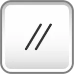
Parallelism is a fairly common symbol that describes a parallel orientation of one referenced feature to a datum surface or line. It can reference a 2D line referenced to another element, but more commonly it relates the orientation of one surface plane parallel to another datum plane in a 3-Dimensional tolerance zone. The tolerance indirectly controls the 0° angle between the parts by controlling where the surface can lie based on the datum. See the tolerance zone below for more details.