Week 9:- 2D Detailing Challenge
1: What are the Drawing templates?
Drawing Templates are the standard drawing files that are used to detail the 3D Models like part modelling, product layout, etc.
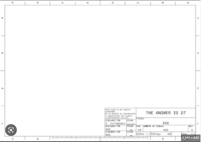
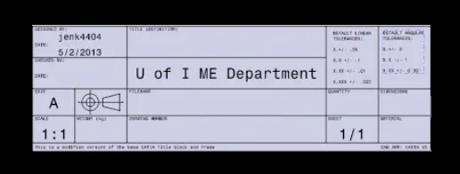
Creation;
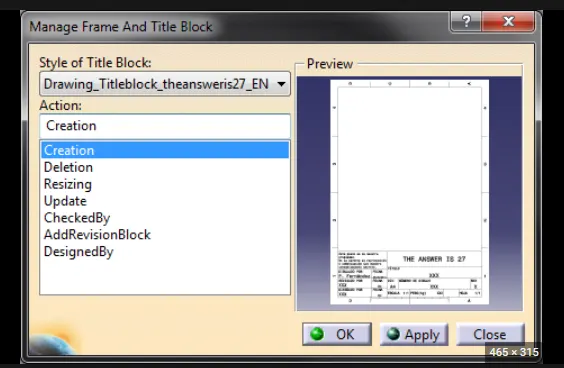
Drawing Templates:
- Drawing templates are basically the drawing standards as per customers specifications.
- Drawing templates are format that are used for detailing of different parts or units of the fixture.
- There are N numbers of details that are already available on the templates & are useful for various manufacturing processes such as machining finish, tolerances, surface treatments, material, name of the assemblies, etc.
- Preparing a drawing template at the start of the project can help us save time, as these templates can be used as a start model for detailing for different parts.
- Drawing templates also gives information about the angle projection to be used, views to be considered scaling of the drawing as per the part or unit.
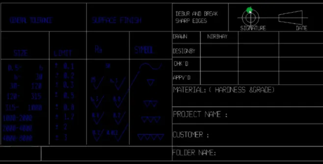
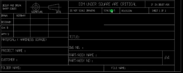
Drawing templates contains a lot of information about the drawing as given below:
- Scale
- GD&T
- Roughness Symbols and standards
- Quantity
- Tolerances
- Sheet size and sheet number
- Type of projection (1st angle or 2nd angle)
- Notes about surface hardening and stress relieving
- Project code
- Part number
- Project name
- Company name
- Title
- Designed and checked by who
- Date
- Mass and density
- Allowance
2: What do you understand by angle of projection?
To define an object, technical drawings use 2D views. This is called as orthogonal projection. The projection of the plane is viewed by the observer. The quadrants it should be only rotated in a clockwise direction.
The angles of projection are basically the view formats for orthogonal views of assemblies or panels. First and third angle of projection are majorly used in automotive standards. Understanding the angles of projection helps us to derive the actual image of 2D drawing.
The orthographic projection system is used to represent a 3D object in a 2D plane. The orthographic projection system utilizes parallel lines, to project 3D object views onto a 2D plane. According to the rule of orthographic projection. To draw a projection view of a 3D object on a 2D Plane. The horizontal plane is rotated in the clockwise direction.
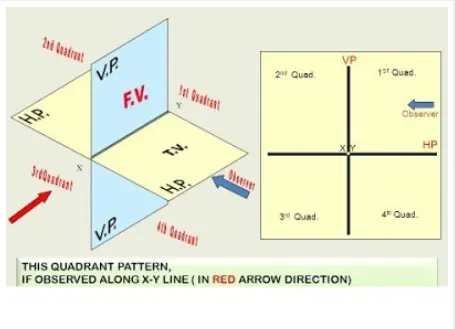
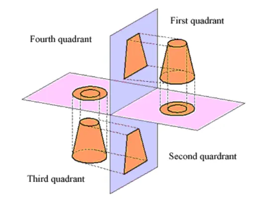
Types of Orthographic projection systems are first angle and third angle projection.
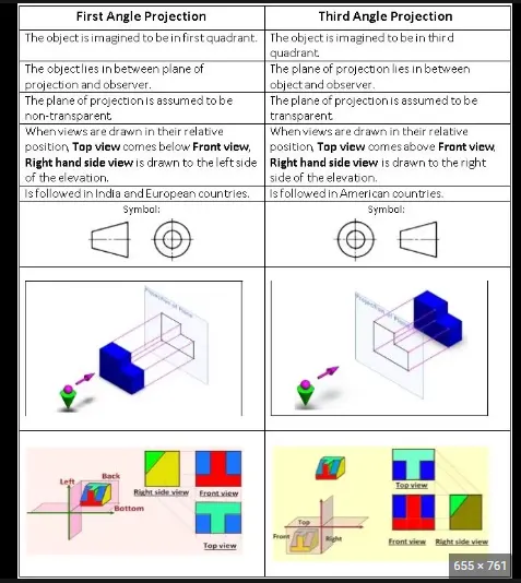
- First Angle Projection:
In the first angle projection, the object is placed in the 1st quadrant. The object is positioned at the front of a vertical plane and top of the horizontal plane. First angle projection is widely used in India and European countries. The object is placed between the observer and projection planes. The plane of projection is taken solid in 1st angle projection.
The object is assumed to be positioned in between the projection planes and the observer. The views are obtained by projecting the image on the respective planes.
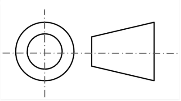
Symbol:– 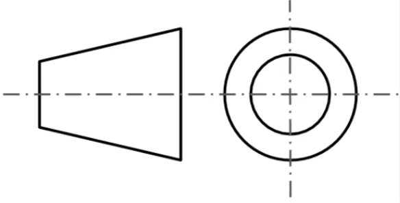
- Third Angle Projection :
In the third angle projection, the object is placed in the third quadrant. The object is placed behind the vertical planes and bottom of the horizontal plane. Third angle projection is widely used in the United States. The projection planes come between the object and observer. The plane of projection is taken as transparent in 3rd angle projection. The projection of plane is assumed to be positioned in between the observer and the object.
Symbol:–
Difference Between 1st angle projection & 3rd angle projection
3: What is First angle & third angle projection? And why cant we use the 2nd angle of projection
First Angle Projection:
In the first angle projection, the object is placed in the 1st quadrant. The object is positioned at the front of a vertical plane and top of the horizontal plane. First angle projection is widely used in India and European countries. The object is placed between the observer and projection planes. The plane of projection is taken solid in 1st angle projection.
Third Angle Projection:
In the third angle projection, the object is placed in the third quadrant. The object is placed behind the vertical planes and bottom of the horizontal plane. Third angle projection is widely used in the United States. The projection planes come between the object and observer. The plane of projection is taken as transparent in 3rd angle projection.
why cant we use the 2nd and 4th angle of projection:
In Second quadrant, Vertical plane (VP) lies in between object and observer. Therefore, front view of the object will lie on vertical plane whereas top view will lie on horizontal plane. As per rule of projection when horizontal plane is rotated 90 degree in clockwise direction, top and front view will overlap.
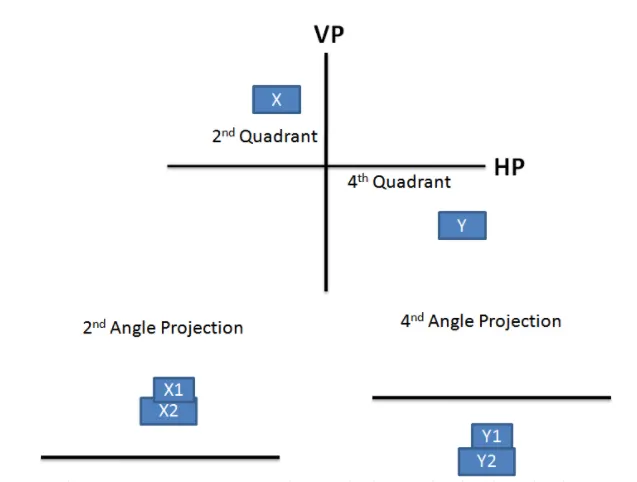
Overlapping projection views create confusion in the drawing. Therefore 2nd angle projection system is not used.
Similarly, when object is placed in 4th quadrant both top and front view will overlap. Therefore, fourth angle projection is also not used.
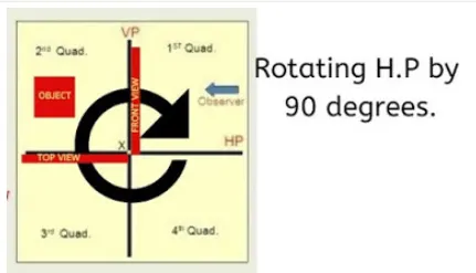
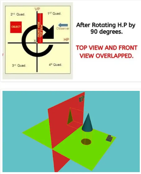
To sum up, because of overlapping of front and top views 2nd and 4th angle projections are not used. First and third angle projection systems are recommended for orthographic projections.
Question No 4: What is GD&T? What are the benefits of GD&T?
ANSWER:
Geometric Dimensioning and Tolerancing (GD&T) is a design approach and manufacturing mechanism that helps engineers and designers communicate how to bring a part design to life. When documented correctly using GD&T, it is possible to build a part that exactly matches its on-paper plans.
GD&T uses a symbolic language to indicate how significantly part features can deviate from the geometries listed in the design model. This language contains all relevant details involved in fabrication, including dimensions, tolerances, definitions, rules, and symbols that communicate a component’s functional requirements.
Benefits of GD&T:
- A standardized design language.
- A clear and precise way for the customer, supplier and production team to communicate.
- A method for calculating the worst case mating limits.
- Production and inspection processes are repeatable.
- Assembly is assured from quality production parts.
- Standardized, international system
- More flexibility, particularly for complex shapes
- Allows cylindrical tolerance zones
- Datums are clearly defined
- Based on the fit and function of a part or assembly
- Eliminates the need for many notes
- Allows for more tolerance
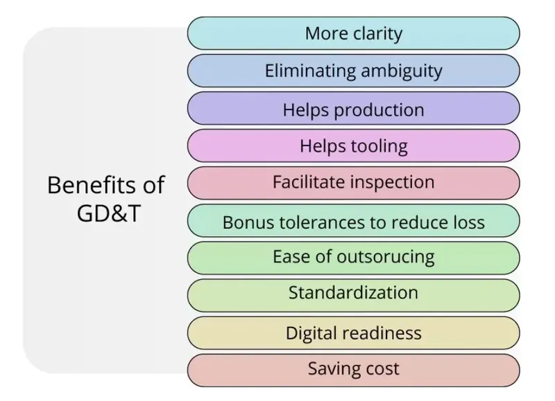
Five Major Advantages
GD&T, a vital part of complex machining, offers a number of major advantages:
Saving Money — GD&T enhances design accuracy by allowing for appropriate tolerances that maximize production. For many projects, the process provides extra or bonus tolerances, further increasing cost effectiveness.
Ensuring Dimensional and Tolerance Requirements — By explicitly stating all design requirements, a thorough GD&T process guarantees accurate fulfillment of all dimensional and tolerance specifications.
Assisting Digital Design Methods — Clear, concise GD&T data is readily adaptable to digital design programs, including nearly universally used 2D and 3D CAD files.
Offering Uniformity and Convenience — As a single, consistent language, GD&T reduces guesswork and interpretation while ensuring consistent geometries across design and manufacturing.
Providing Accurate Communication — Today’s intricate designs demand the most accurate and reliable communication. GD&T enables designers, manufacturers, and inspectors to communicate clearly with one other, saving time and making the process more efficient.
When to Use GD&T:
- While many applications benefit from GD&T, there are certain situations in which the process provides fundamental assistance, including scenarios in which critical or interchangeable parts fit into a larger assembly, tolerance analysis needs simplification, or the project requires functional gauging techniques.
- GD&T replaces complex description notes with a single symbol or set of symbols, allowing for effortless reference and fast, precise communication. The process provides additional clarity when clients are working without a standard interpretation or tolerance, making even the most in-depth and complicated projects easier to complete.
5; Explain all the symbols used in GD&T?
Answer is please refer the below attached image.