Week 9:- 2D Detailing Challenge
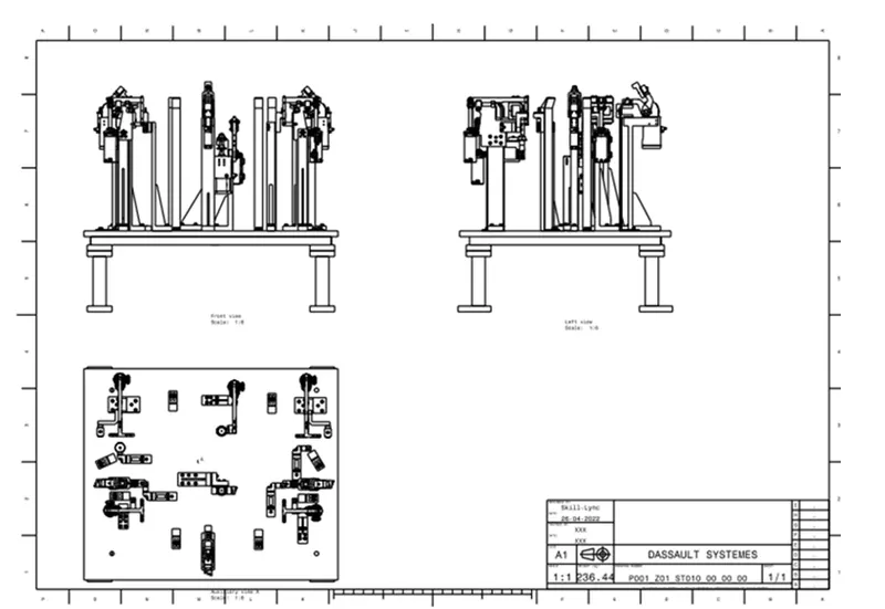
What are drawing templates?
Compared to conveying data in verbal or written form, symbols and drawing provide information in a better and more understandable way minimizing errors caused by miscommunications or misunderstandings.
- Drawing templates are standards decided by the client.
- Drawing templates are used to define all the parts or various parameters in a fixture in a systematic manner.
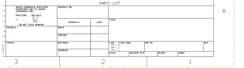
- Drawing templates are usually of .dwg extension and have a blank page with a frame for the filing of details with set styles, and setting for title blocks.
- There are various details present on the template which can be edited as per the requirements and space for adding required notes for the manufacturing process or details like finishing, tolerances, name of parts, name of the assembly, etc.
- Drawing templates are usually created at the start of the project as they can be used as a base for all the detailing files that follow.
- Drawing templates can be different for different sheet sizes.
Need for templates:
They are needed to set the view display, place notes if any for the manufacturing process, and place symbols wherever necessary for easy understanding or 2D Drawing.
Define tables and show the dimensions of the setup. The templates for machined parts cast parts, and the likes are different.
Templates are made for the purpose, that part of the detailing process is already done at the start of detailing. Hence, templates should be created such that they reduced the work during the detailing process.
Templates should contain the following information in addition to other info particular to the project.
- Company name
- Project name
- Sheet size
- Quantity
- Scale
- Date
- Unit of measurement
- Revision date
- Drawn by
- Angle of projection
- Sheet numbe
What do you understand by the angle of projection?
The angle at which the observer looks at an object and draws it in 2D from 3D from a real object to paper is called the angle of projection.
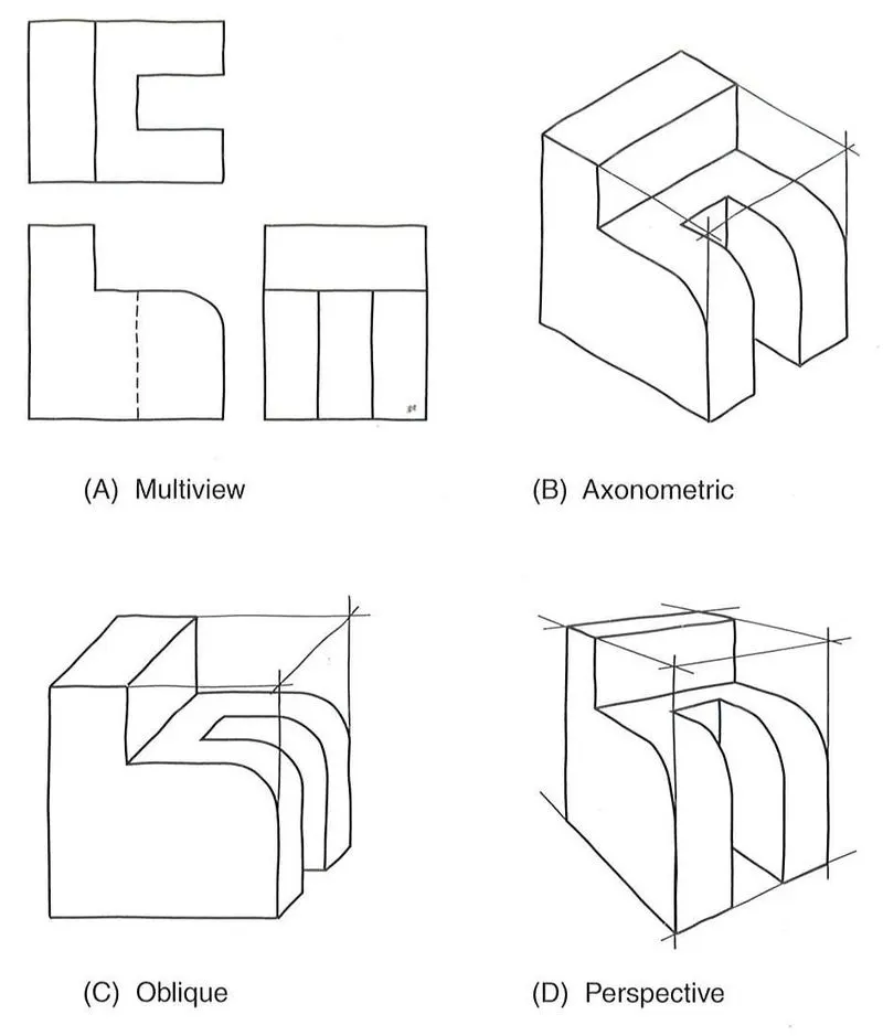
Parallel projection is used to generate drawing which is used for manufacturing the part. The angle of projection is usually perpendicular to the object. A plane is an imaginary surface on which pictures are drawn. Usually, a minimum of 3 views of the object are required to be able to present all the dimensions required for manufacturing.
When two planes one horizontal and one vertical are considered principal planes. These planes are placed such that they form 4 quadrants. When the object is placed in 1 quadrant it is called first angle projection, i.e., the plane is behind the object. When an object is placed in the 3rd quadrant, it is called 3rd angle projection, i.e., the object is behind the plane.
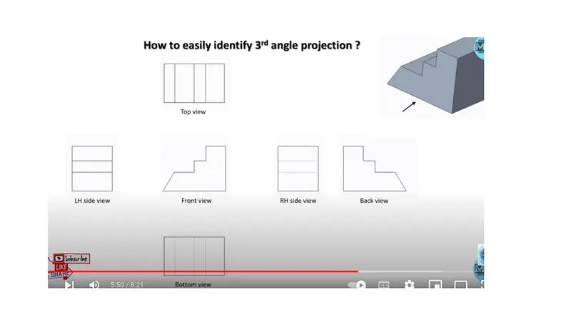
In orthographic projection there are the following views:
- Front view
- Top view
- Back view
- Bottom view
- Right side view
- Left side view
What is the First angle & Third angle projection? and why can't we use the 2nd and 4th angle of projection?
First Angle Projection
It is videly used in india and european country
- In this projection object is assumed to be positioned in the first quadrant
- The object is assumed to be positioned in between the projection planes and the observer_Plane-object -observer.
- The views are obtained by projecting the images on the respective planes.
This is one of the most common methods used to obtain engineering drawings, mostly for orthographic projections. Orthographic projection is a graphical method used to represent three-dimensional structures or objects into different perspective projection images called views. The orthographic view typically consists of the top view, front view, and the side view. First angle projection is one of the methods used for orthographic projection drawings and is approved internationally except the United States. In this projection method, the object is placed in the first quadrant and is positioned in front of the vertical plane and above the horizontal plane.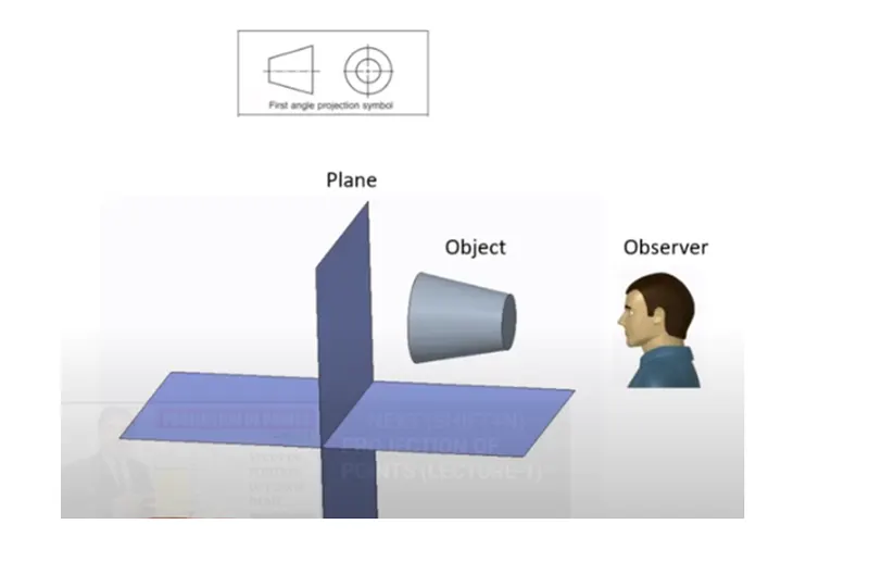
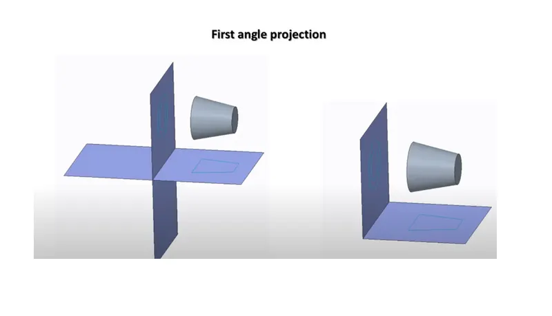
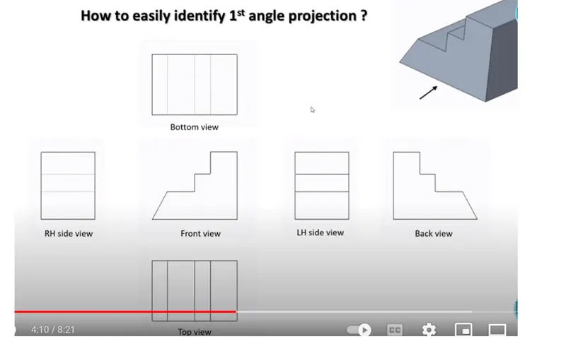
Third Angle Projection
It is widely used in US and Austrailia
- Here the object is assumed to be in the third quadrant ie the object behind the vertical plane and below the horizontal plane
- In this projection technique placing the object in the third quadrant puts the projection planes between the viewer and the object_object-plane -observer.
This is another perspective projection method used to represent three-dimensional objects using a series of two-dimensional views. In third angle projection, the 3D object to be projected is placed in the third quadrant and is positioned behind the vertical plane and below the horizontal plane. Unlike in first angle projection where the plane of projection is supposedly opaque, the planes are transparent in third angle projection. This projection method is mainly used in the United States and Japan stipulates the use of third angle projection schema for industrial designs for product fabrication.
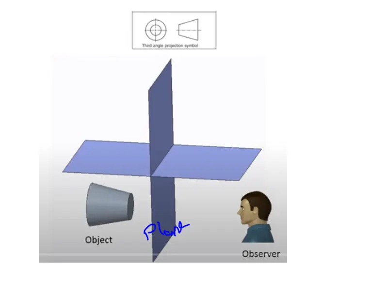
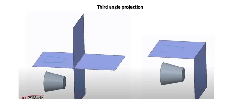
Let us first understand the concept behind the angle projection system. Imagine you have Vertical Plane (VP) and Horizontal Plane (HP) (Perpendicular to each other), now we have 4 quadrants. For the 1st angle projection system, we place an object in the 1st quadrant, for the 2nd angle projection system, we place an object in 2nd quadrant and so on.
In the second quadrant, the Vertical plane (VP) lies between object and observer. Therefore the front view of the object will lie on a vertical plane whereas the top view will lie on a horizontal plane. As per the rule of projection when the horizontal plane is rotated 90 degrees in a clockwise direction, the top and front views will overlap. Similarly when the object is placed in the 4th quadrant both the top and front views will overlap. Therefore fourth angle projection is also not used. Overlapping projection views create confusion in the drawing. Therefore 2nd angle projection system is not used.
What is GD&T? What are the benefits of GD&T?
Geometric Dimensioning and Tolerance is a language of symbol and standard communication between entities working together to produce part/components. By depending on your knowledge around have to create a good structure of GD &T you will improve communication with your machine shop and ensure everyone involved is speaking the same language.
The Benefits of the GD & T are:-
- A standardised design language all over the country.
- A clear and precise way for the customers' supplies and production teams to communicate
- A method for calculating the worst-case mating limits.
- Production and inspection processes are repeatable
- Assemblies are assured of qualified production parts.
Explain all the symbols used in GD&T?
Symbols of Geometric characteristics are what most often come to mind when people think about GD & T these are a total of fourteen GD & T characteristics and the symbols. Most frequently used GD&T symbles are presented in tje below table.
| GD&T Symbol | Control Type | Name | Summary Description |
| Form | Straightness | Controls the straightness of a feature in relation to its own perfect form | |
| Form | Flatness | Controls the flatness of a surface in relation to its own perfect form | |
| Form | Circularity | Controls the form of a revolved surface in relation to its own perfect form by independent cross sections | |
| Form | Cylindricity | Like circularity, but applies simultaneously to entire surface | |
| Profile | Profile of a Surface | Controls size and form of a feature. In addition it controls the location and orientation when a datum reference frame is used. | |
| Profile | Profile of a Line | Similar to profile of a surface, applies to cross sections of a feature | |
| Orientation | Perpendicularity | Controls the orientation of a feature which is nominally perpendicular to the primary datum of its datum reference frame | |
| Orientation | Angularity | Controls orientation of a feature at a specific angle in relation to the primary datum of its datum reference frame | |
| Orientation | Parallelism | Controls orientation of a feature which is nominally parallel to the primary datum of its datum reference frame | |
| Location | Position | Controls the location and orientation of a feature in relation to its datum reference frame | |
| Location | Concentricity | Controls concentricity of a surface of revolution to a central datum | |
| Location | Symmetry | Controls the symmetry of two surfaces about a central datum | |
| Runout | Circular runout | Controls circularity and coaxiality of each circular segment of a surface independently about a coaxial datum | |
| Runout | Total runout | Controls circularity, straightness, coaxiiality, and taper of a cylindrical surface about a coaxial datum |
| Symbol | Meaning |
| LMC – Least Material Condition |
|
| MMC – Maximum Material Condition |
|
| Tangent Plane | |
| Projected Tolerance Zone | |
| Free State | |
| Diameter | |
| Radius | |
| Spherical Radius | |
| Spherical Diameter | |
| Controlled Radius | |
| Statistical Tolerance | |
| Basic Dimension | |
| Reference Dimension | |
| Places |
| Symbol | Meaning |
| Dimension Origin | |
| Counterbore | |
| Countersink | |
| Depth | |
| All Around | |
| Between | |
| Target Point | |
| Conical Taper | |
| Slope | |
| Square |