Week 9:- 2D Detailing Challenge
Automotive BIW Fixture Design
Assignment
By Ravi Ahuja
Q1.
A drawing template enables you to create exact circles, squares, lines, arcs, and more without reaching for a compass, ruler, or protractor. It’s a necessary tool for executing clean-lined blueprints, sketches that demand precision, or crisp compositions for bullet journals.
There are 5 types of Drawing Templates.
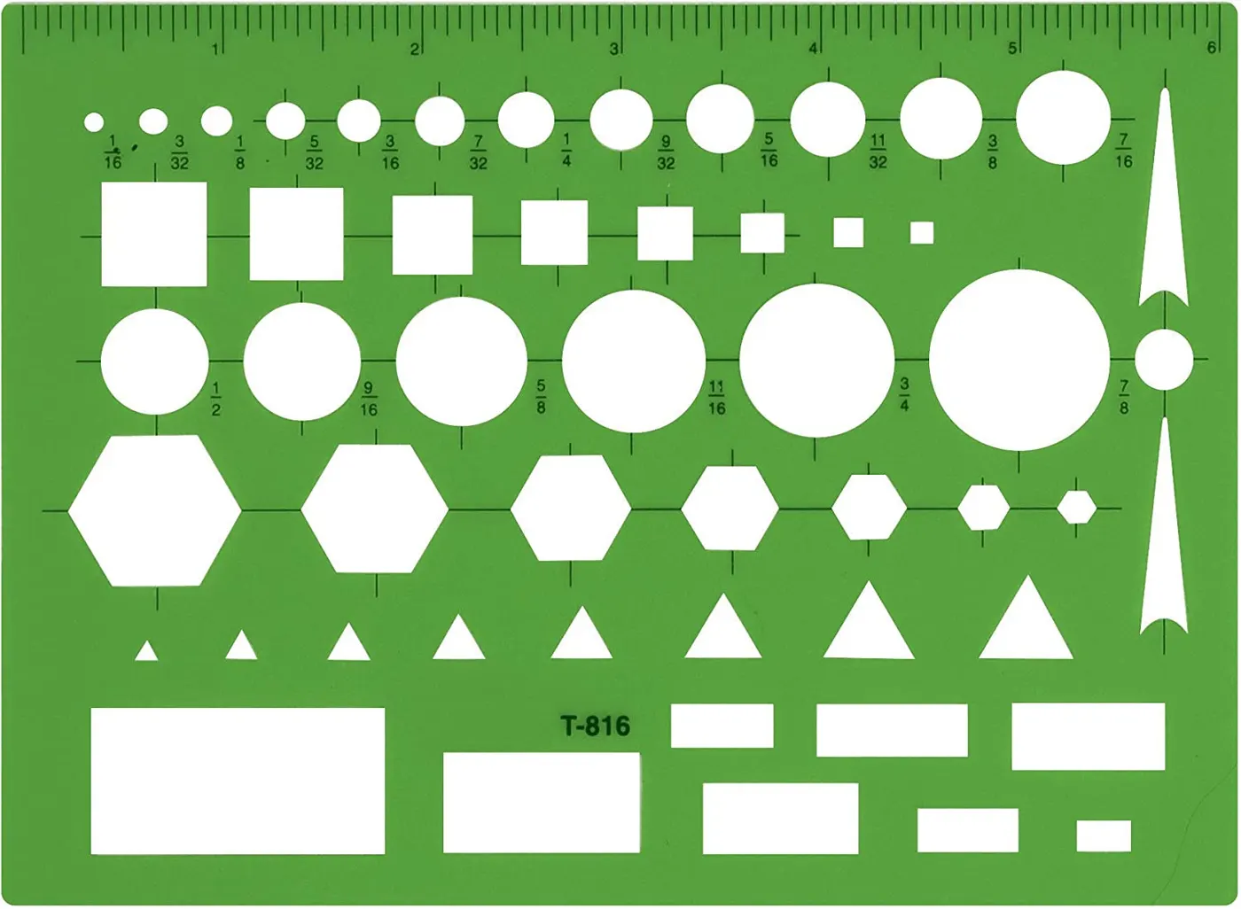
1. Westcott technical all purpose drawing template
A versatile tool that can be used for drafting or doodling, Westcott’s template features an inch scale and a range of die-cut shapes—circles, squares, hexagons, rectangles, and triangles—in different sizes. Circles and squares are handily labeled according to their diameter, and lines marking the center of each shape’s sides offer additional guidance for accuracy. There’s a balanced amount of information on this sturdy green tool: While professional drafters can make use of the basic measurements, others won’t be overwhelmed by numbers and can enjoy the simple act of tracing shapes.
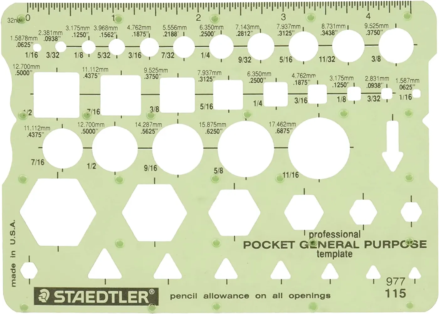
2. Staedtler technical drawing template
More technical and specialized than our top pick, this German-made pocket template is equipped with more than a few measurements to draw circles, squares, triangles, and hexagons. Architects will appreciate that the shapes are annotated with both fractional and decimal inch measurements as well as millimeter notations and tick marks marking center lines. Made of a pleasing green plastic that is impact resistant, this template won’t quickly wear down even with daily use.
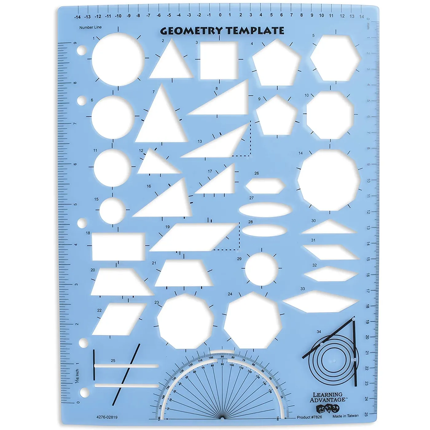
3. Learning advantage geometry template
This basic template feels flimsier than the competition, but it’s well suited for young artists who need to get a feel for geometry. It’s stripped down to feature cutouts of dozens of shapes, from pentagons to rhombuses, each labeled with its midlines. A centering scale, an edge for inches and another for millimeters, and a protractor top it off. Use it to trace shapes without the distraction of the dense numbering found on more technical tools.
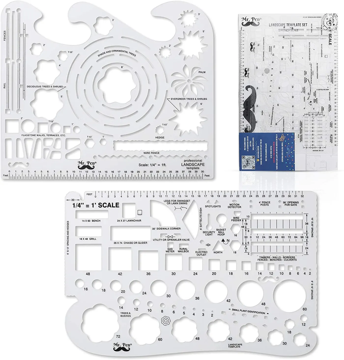
4. Mr. Pen Architectural and landscape templates
If your projects involve landscape design, choose this pair of thoughtfully laid out templates. They feature lots of well-cut openings for drawing precise features such as shrubbery, spotlights, and flagstone walks. Items are clearly labeled, with dimensions provided for certain objects including fenceposts and lawn chairs. Constructed of durable clear plastic with enough flex to wrap around a curved surface, these templates are tough to beat.
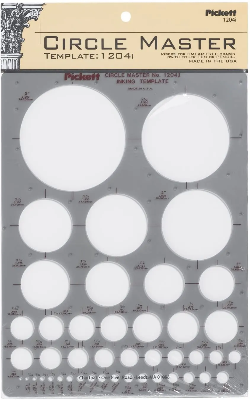
5. Pickett circle mster template
A good circle template can be hard to find. End your search with Pickett’s product, which features dozens of precisely cut circles for seamless tracing. Each is labeled with its diameter—ranging from 1/16 inch to 3 inches—both in inches (shown as fractions and decimals) and in millimeters. What makes it stand out from most of the competition are the integrated risers that subtly elevate the smoke-gray plastic (made of partially recycled materials) to prevent smudging if you’re drawing with ink.
Q2.
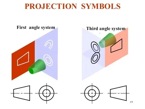
The angle at which an observer draw an object to convert it from 3d to 2d plane such as real object image to a plane paper is known as angle of projection. There are two anlge of projection used in drawing.:
- First angle of projection(First quadrant)
- Third angle of projection(3rd quadrant of cooradinate plane)
Q3.
First angle Projection:
First angle projection is one of the methods used for orthographic projection drawings and is approved internationally except the United States. In this projection method, the object is placed in the first quadrant and is positioned in front of the vertical plane and above the horizontal plane.
Third angle Projection:
In third angle projection, the 3D object to be projected is placed in the third quadrant and is positioned behind the vertical plane and below the horizontal plane. Unlike in first angle projection where the plane of projection is supposedly opaque, the planes are transparent in third angle projection. This projection method is mainly used in the United States and Japan stipulates the use of third angle projection schema for industrial designs for product fabrication.
Representation of First and tird angle projection:
To get the first angle projection, the object is placed in the first quadrant meaning it’s placed between the plane of projection and the observer. For the third angle projection, the object is placed below and behind the viewing planes meaning the plane of projection is between the observer and the object.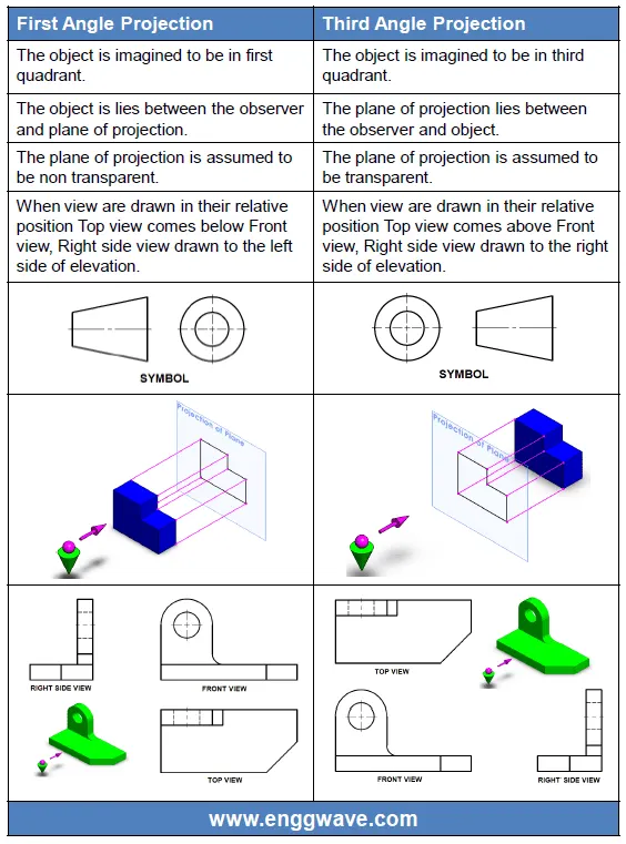
Q4.
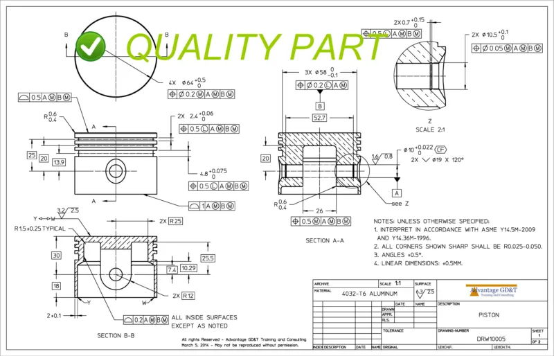
Geometric Dimensioning and Tolerancing (GD&T) is a design approach and manufacturing mechanism that helps engineers and designers communicate how to bring a part design to life. When documented correctly using GD&T, it is possible to build a part that exactly matches its on-paper plans.
The drawing is the controlling document that ensures the vendor is creating precisely what the customer’s design requires. Machinists and quality engineers will use GD&T, print dimensions, and drawing notes to develop a manufacturing process and inspection methodology that will construct high-precision components matching the designer’s original vision. Proper print detailing will also help with measurement correlation to aid in the communication between customer and vendor.
GD&T uses a symbolic language to indicate how significantly part features can deviate from the geometries listed in the design model. This language contains all relevant details involved in fabrication, including dimensions, tolerances, definitions, rules, and symbols that communicate a component’s functional requirements. These all currently follow ASME Y14.5M-2009 (previously ASME Y14.5M-1994).
Engineers and designers look to GD&T to design critical aspects of a part’s features, including a specific feature’s desired location, form, profile and orientation. It is common practice to use the profile designation tied to the datum structure that is related back to the solid CAD model. This allows Manufacturing to use a best fit protocol.
Five Major benefits:
- Saving Money — GD&T enhances design accuracy by allowing for appropriate tolerances that maximize production. For many projects, the process provides extra or bonus tolerances, further increasing cost effectiveness.
- Ensuring Dimensional and Tolerance Requirements — By explicitly stating all design requirements, a thorough GD&T process guarantees accurate fulfillment of all dimensional and tolerance specifications.
- Assisting Digital Design Methods — Clear, concise GD&T data is readily adaptable to digital design programs, including nearly universally used 2D and 3D CAD files.
- Offering Uniformity and Convenience — As a single, consistent language, GD&T reduces guesswork and interpretation while ensuring consistent geometries across design and manufacturing.
- Providing Accurate Communication — Today’s intricate designs demand the most accurate and reliable communication. GD&T enables designers, manufacturers, and inspectors to communicate clearly with one other, saving time and making the process more efficient.
Q5.

True Position
Position is one of the most useful and most complex of all the symbols in GD&T. The two methods of using Position discussed on this page will be RFS or Regardless of Feature Size and under a material condition (Maximum Material Condition or Least Material Condition). Position is always used with a feature of size.

Datum Feature
A datum is theoretical exact plane, axis or point location that GD&T or dimensional tolerances are referenced to. You can think of them as an anchor for the entire part; where the other features are referenced from. A datum feature is usually an important functional feature that needs to be controlled during measurement as well.

Profile of a surface
Profile of a surface describes a 3-Dimensional tolerance zone around a surface, usually which is an advanced curve or shape...

Maximum Matrial Condition
Maximum Material Condition (MMC), is a feature of size symbol that describes the condition of a feature or part where the maximum amount of material (volume/size) exists within its dimensional tolerance.
FLatness
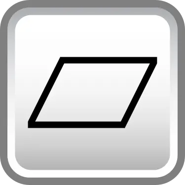
GD&T Flatness is a common symbol that references how flat a surface is regardless of any other datum’s or features. It comes in useful if a feature is to be defined on a drawing that needs to be uniformly flat without tightening any other dimensions on the drawing. The flatness tolerance references two parallel planes (parallel to the surface that it is called out on) that define a zone where the entire reference surface must lie.

Concentricity
Concentricity, sometimes called coaxially, is a tolerance that controls the central axis of the referenced feature, to a datum axis....
Perpendicularity
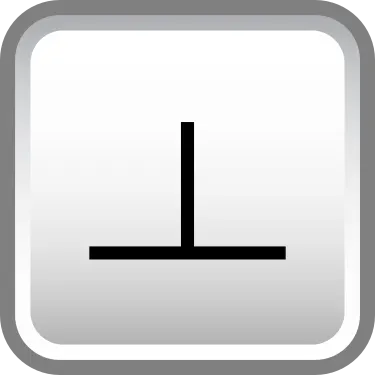
Perpendicularity is a fairly common symbol that requires the referenced surface or line to be perpendicular or 90° from a datum surface or line...

Runout
Runout is how much one given reference feature or features vary with respect to another datum when the part is rotated 360° around the datum axis.

Parellelism
Parallelism is a fairly common symbol that describes a parallel orientation of one referenced feature to a datum surface or line...
Circularity
The circularity symbol is used to describe how close an object should be to a true circle...

Straightness
The standard form of straightness is a 2-Dimensional tolerance that is used to ensure that a part is uniform across a surface or feature. Straightness can apply to either a flat feature such as the surface of a block, or it can apply to the surface of a cylinder along the axial direction. It is defined as the variance of the surface within a specified line on that surface.

Total Runout
Total Runout is how much one entire feature or surface varies with respect to a datum when the part is rotated 360° around the datum axis...

Cylindricity
The Cylindricity symbol is used to describe how close an object conforms to a true cylinder...

Feature Control Frame
In GD&T, a feature control frame is required to describe the conditions and tolerances of a geometric control on a part's feature...

Symmetry
GD&T Symmetry is a 3-Dimensional tolerance that is used to ensure that two features on a part are uniform across a datum plane...

Angularity
Angularity is the symbol that describes the specific orientation of one feature to another at a referenced angle...

Least Material condition
Least material condition is a feature of size symbol that describes a dimensional or size condition where the least amount of material (volume/size) exists within its dimensional tolerance...

Profile of a line
Profile of a line describes a tolerance zone around any line in any feature, usually of a curved shape...
Regardless of feature size
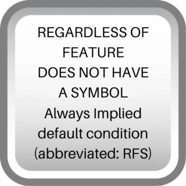
Regardless of feature size simply means that whatever GD&T callout you make, is controlled independently of the size dimension of the part. RFS is the default condition of all geometric tolerances by rule #2 of GD&T and requires no callout.

Envelope Principle
GD&T Rule #1, also known as the Envelope principle, states that the form of a regular feature of size is controlled by its “limits of size." Limits of size, or otherwise known as size tolerances, can be seen in many forms. A few of them are symmetric, unilateral, and bilateral.

Unequally disposed profile
The unequally disposed profile tolerance symbol is used to apply unilateral or unequal tolerance zones to a profile of a part.

Indepedency
The Independency symbol is used on drawings to declare that the requirement for perfect form at MMC or LMC is removed and the form tolerance may be larger than the size tolerance. This symbol only exists in the ASME Y14.5 standards, not the ISO GPS standards.

Envelope Requirement for ISO only
The Envelope Requirement Symbol is used on ISO drawings to declare that size is to control form with respect to perfect form at MMC.

Datum Target
The Datum Target Symbol is used to define a specific point, line, or area to be used in order to establish a datum on a drawing.