Week 9:- 2D Detailing Challenge
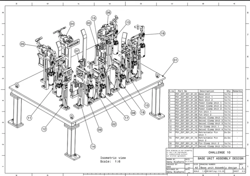
1. Drawing Templates:- A drawing template is a standard template that is used in 2D detailing of the fixture component or assembly. These standard templates are either provided by the customer or by the organization that defines the projection views of the component, GD and T, machining, roughness etc.
While detailing, a drawing template plays a very important role because it helps the manufacturer/production team to understand the engineering process that need to be taken place while finishing a part/assembly. It also defines the material grades to be used, roughness values, welding thicknesses etc.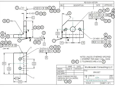
2. Angle of Projection: These are the projection views placed by observer for an object over a plane in all the four quadrants. But out of four quadrants we only use two quadrants that defines the 2D detailing for given angle of projection.
We only use first angle and third angle of projection which are in the first quadrant(first angle) and third quadrant(third angle) respectively. In first quadrant the object is kept in between observer and plane so the respective images for the same are formed at the back side of the object i.e opposite side which is the plane. Whereas in third quadrant the plane comes between observer and object hence the respective image of object is formed in front of the object. 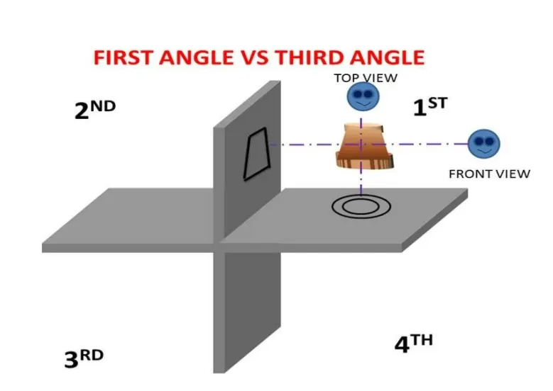
3.
| FIRST ANGLE OF PROJECTION | THIRD ANGLE OF PROJECTION |
| The object is placed in the first quadrant | The object is placed in the third quadrant |
| Object is in between Plane and Observer | Plane is in between Observer and object |
| Plane here is considered to be non transparent while projecting views | Plane here is considered to be transparent for projecting views. |
| In this image of object is formed on the opposite side i.e Front view is at the back, Top view is at the bottom and right side view is on the left side | In this image of object is formed at the front side i.e. Front view is on the front, Top view is at the top and right side view is at the right hand side. |
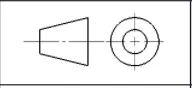 |
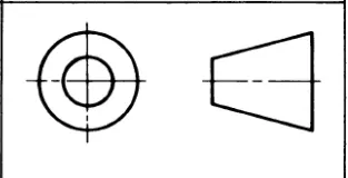 |
We do not use second and fourth angle of projections which are in the second and fourth quadrant because as we know these projections are defined by rotating the horizontal plane anticlockwise by 90 degree each time we move to next quadrant, so when we rotate the plane, the horizontal plane comes parallel to vertical plane which confuses the user with the correct images of the object in these two quadrants. Hence the images are not formed on these. So we prefer to use on First and Third angle of projections.
4. GD & T: It stands for Geometric Dimensioning and Tolerances, which are the engineers language, that helps him communicate with production and manufacturers by using some standard symbols of GD and T to define the orientation, form and location of the component.
The following benefits of GD and T are:
- It helps the manufacturer in understanding the machining operations and its types to be used which developing a component.
- It also helps the manufacturer in understanding the position/location of holes with respect to datum planes.
- It helps in tooling and eliminating the ambiguity of parts.
- It is very cost effective
- It helps in standardisation and bonus tolerances for outsourcing
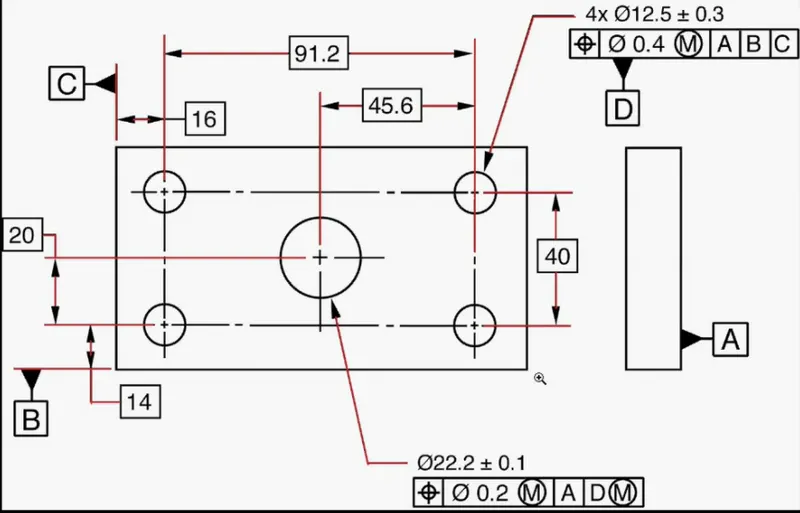
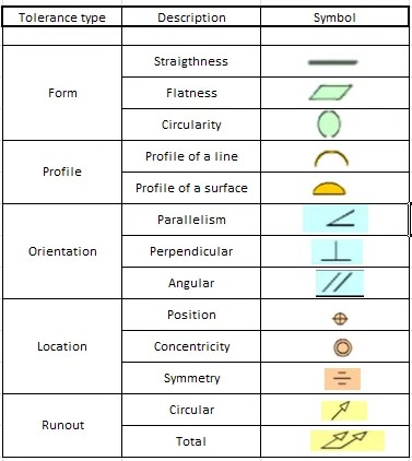
5. There are 14 symbols in GD & T which are categorized in following five tolerance types:
5.1: Form: It controls the shape of the feature and used as refining the size of the feature.
5.2: Orientation: It controls the tils of feature with angles. If it is applied to surfaces , it can control form of the feature.
5.3: Location: It controls the location associated with linear dimension.
5.4: Profile: It is similar to location tolerance which when applied to surfaces the controls the profile of the features.
5.5: Runout: This controls the coaxiality of the feature.