Week 9:- 2D Detailing Challenge
1.What are the Drawing templates?
Drawing templates may be referenced when creating a new drawing. They automatically create the views, set the desired view display, create snap lines, and show model dimensions based on the template.
Drawing templates contain three basic types of information for creating new drawings. The first type is basic information that makes up a drawing but is not dependent on the drawing model, such as notes, symbols, and so forth. This information is copied from the template into the new drawing.
The second type is instructions used to configure drawing views and the actions that are performed on that view. The instructions are used to build a new drawing with a new drawing object (model).
The third type is parametric notes. Parametric notes are notes that update to new drawing model parameters and dimension values. The notes are re-parsed or updated when the template is instantiated.
Use the templates to:
• Define the layout of views
• Set view display
• Place notes
• Place symbols
• Define tables
• Create snap lines
• Show dimensions
2.What do you understand by Angle of projection?
The angle at which an observer draw an object to convert it from 3D to 2D plane such as real object image to a plane paper is known as angle of projection.
The angle between the initial velocity of a body from a horizontal plane through which the body is thrown, is known as angle of projection
3.What is the First angle & Third angle projection?
To get the first angle projection, the object is placed in the first quadrant meaning it's placed between the plane of projection and the observer. For the third angle projection, the object is placed below and behind the viewing planes meaning the plane of projection is between the observer and the object.
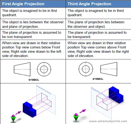
why can't we use the 2nd and 4th angle of projection?
As per rule of projection when horizontal plane is rotated 90 degree in clockwise direction, top and front view will overlap. ... Therefore 2nd angle projection system is not used. Similarly when object is placed in 4th quadrant both top and front view will overlap. Therefore fourth angle projection is also not used.
4. What is GD&T?
GD&T Geometric Dimensioning and Tolerancing is defined as an international language used for communicating engineering design specifications based on the function and intent of part features. This engineering language uses the necessary definitions, symbols, and application rules to clearly document the nominal geometry as well as the acceptable variation of the features. This includes the functional requirements of a manufactured assembly part and to ensure the compatibility and interchangeability of those parts.
What are the benefits of GD&T?
- Standardized, international system.
- More flexibility, particularly for complex shapes.
- Allows cylindrical tolerance zones.
- Datums are clearly defined.
- Based on the fit and function of a part or assembly.
- Eliminates the need for many notes.
- Allows for more tolerance
5. Explain all the symbols used in GD&T?
In geometric dimensioning and tolerancing (GD&T), a unique set of GD&T symbols are used to define the relationships between part features and measurement references. ... Understands the effect of the GD&T on product function, manufacturing, inspection, and assembly.