2D Detailing Challenge
What are the Drawing templates?
Drawing templates are the files of frames and title block which convey the design information that are used to generate 2 D drawing from 3 D part.
Neat and detailed Drawing templates convey more information from designer to manufacturer. so we can avoid misunderstanding and make a very effective parts, which saves time and money.
Drawing templates are change as per the company standards. Drawing templates are provide by the customer at the starting of the project ,if not then we should finalize at starting of project.
Drawing templates has n number of information such as:
- Company name
- Project Name
- Sheet size
- Sheet number
- Angle of projection
- Revision Number/latter(if its revision drawing)
- Signature or name of drawn by, checked by, responsible engineer and approved by
- Parts detail
- Quantity
- Additional notes(Surface finish,heat treatment, material detail, etc)
- Scale, date,unit of measurement
What do you understand by Angle of projection?
The angle at which an observer draw an object to convert it from 3D to 2D plane such as real object image to a plane paper is known as angle of projection. There are two angle of projection used in drawing:
- 1st angle of projection(first quadrant of coordinate plane)
- 3rd angle of projection(3rd quadrant of coordinate plane)
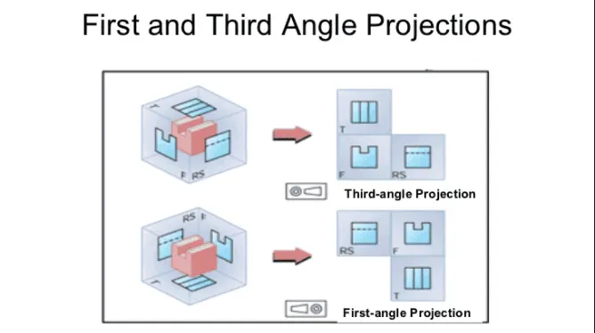
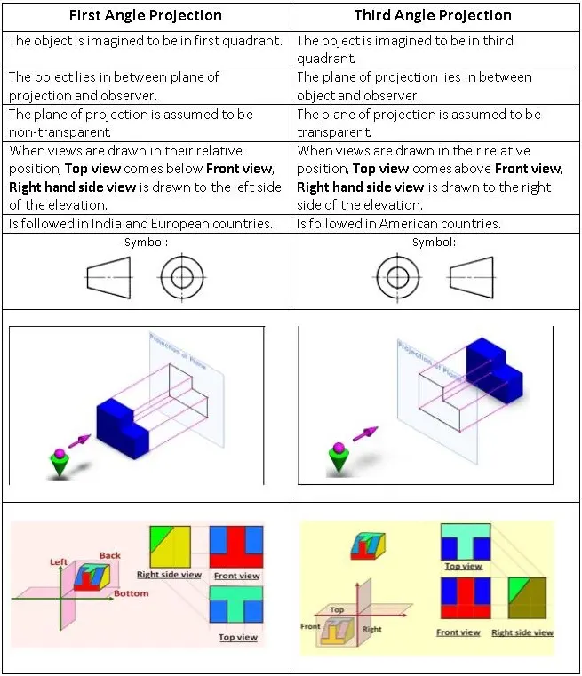
What is the First angle & Third angle projection? and why can't we use the 2nd and 4th angle of projection?
First Angle Projection :
In the first angle projection, the object is placed in the 1st quadrant. The object is positioned at the front of a vertical plane and top of the horizontal plane. First angle projection is widely used in India and European countries. The object is placed between the observer and projection planes. The plane of projection is taken solid in 1st angle projection.
Third Angle Projection :
In the third angle projection, the object is placed in the third quadrant. The object is placed behind the vertical planes and bottom of the horizontal plane. Third angle projection is widely used in the United States. The projection planes come between the object and observer. The plane of projection is taken as transparent in 3rd angle projection.
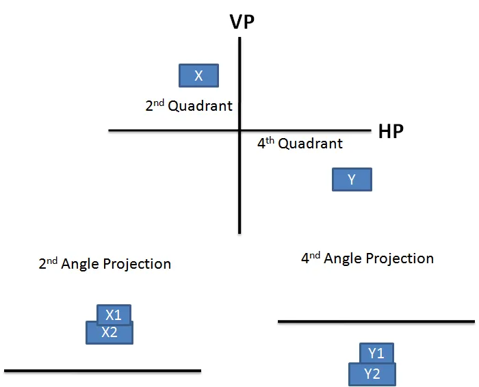
Second and fourth angle projection system has some limitations. Therefore only First and Third angle projection Systems are used to prepare engineering drawings. In this article we will discuss the limitations of 2nd and 4th angle projection. To understand why 2nd and 4th angle projection are not used? Firstly we need to understand the concept behind the orthographic projection system.
Let’s consider a point in A and B in 1st and 3rd quadrant respectively. As per rule of projection, to bring drawing views from three dimensional to two dimensional planes. Horizontal plane (HP) is rotated in the clockwise direction.
In the Second quadrant, vertical plane (VP) lies in between object X and observer. Therefore the front view of object x will lie on vertical plane whereas top view will lie on horizontal plane. As per rule of projection when horizontal plane is rotated 90 degree in clockwise direction, top and front view will overlap.
Overlapping projection views in 2nd and fourth angle projection create confusion in the drawing.
Overlapping projection views create confusion in the drawing. Therefore the 2nd angle projection system is not used.
Similarly when the object is placed in 4th quadrant both top and front view will overlap. Therefore fourth angle projection is also not used.
What is GD&T? What are the benefits of GD&T?
Geometric Dimensioning and Tolerancing (GD&T) is a system for defining and communicating engineering tolerances. It uses a symbolic language on engineering drawings and computer-generated three-dimensional solid models that explicitly describe nominal geometry and its allowable variation.
Benefits of GD&T
Saving Money — GD&T enhances design accuracy by allowing for appropriate tolerances that maximize production. For many projects, the process provides extra or bonus tolerances, further increasing cost effectiveness.
Ensuring Dimensional and Tolerance Requirements — By explicitly stating all design requirements, a thorough GD&T process guarantees accurate fulfillment of all dimensional and tolerance specifications.
Assisting Digital Design Methods — Clear, concise GD&T data is readily adaptable to digital design programs, including nearly universally used 2D and 3D CAD files.
Offering Uniformity and Convenience — As a single, consistent language, GD&T reduces guesswork and interpretation while ensuring consistent geometries across design and manufacturing.
Providing Accurate Communication — Today’s intricate designs demand the most accurate and reliable communication. GD&T enables designers, manufacturers, and inspectors to communicate clearly with one other, saving time and making the process more efficient.
Explain all the symbols used in GD&T?
The table above shows different symbols used in GD & T. In the form tolerance we have straightness which indicates the striaghtness of the part surfaces. Flatness indicates the flatness of the surfaces of the parts, similary the circularity and cylindricity indicates about the holes.
In the profile tolerance the profile of the line or te surface are indicated by the semi arc and semi circle respectively. In the orientation tolerances the angular, perpendicular and parallel orientations are defined.
In the location tolerances the position, concentricity and symmetry of the parts are indicated. in runout tolerances the circular run out which is given at a particular place or portion of te part where as total runout is given to the whole part