Week 8 Worm Gear Challenge
AIM
- To perform a transient structural analysis on a worm gear assembly.
OBJECTIVE
- The challenge is to simulate the transient structural analysis on a worm gear assembly using the Ansys workbench to perform the analysis on the student version the heart contains with over-limit bodies which need to be cut down and evaluate the results by refining the mesh.
THEORY
- The worm gear is a gear arrangement in which a worm (which is the ger in the form of a screw) meshes with a worm gear ( which is similar in appearance to a spur gear). The two elements are also called the worm screw and worm wheel. The terminology is often confused by the imprecise use of the term worm gear to refer to the worm gear or the worm drive as a unit.
- There are three different types of gears that can be used in a worm drive.
- The first is non - throated worm gears. These don't have a throat or groove machined around the circumference of either the worm or worm wheel. The second is single-throated worm gears, in which the worm wheel is throated. The final type is double-throated worm gears, which have both gears throated. This type of gearing can support the highest loading.
- An enveloping (hourglass) worm has one or more teeth and increases in diameter from its middle portion toward both ends.
- Double-enveloping worm gearing comprises enveloping worms mated with fully enveloping wormgears. It is also known as globoid worm gearing.
MATERIAL PROPERTIES
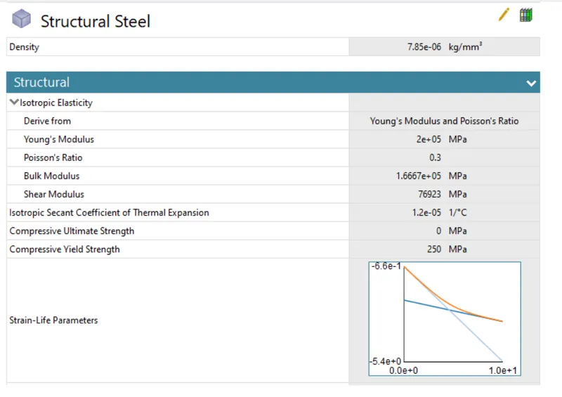
- Structural Steel
Geometry
- The geometry is with many faces that exceed the student academic limit, so the bottom part of the gear is cut down and reduces the faces so that geometry could accept the simulation process for the academic version.
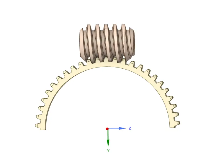
- In the mechanical module opening the geometry and then renaming the part to consider by their name-based definition for connections. As we are using only the structural steel material.
Connections
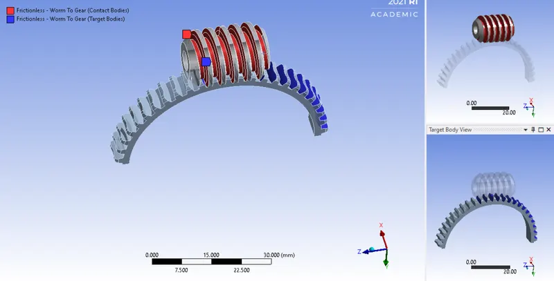
- The contact renamed based on the definition and adding a few targets of the gear for rotating the worm on the gear. The total number of contacts of the worm - 9 faces and the contact faces - 31 Faces and the types to be used as frictionless.
Joints
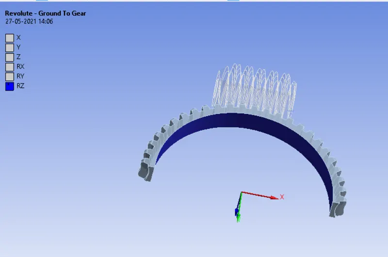
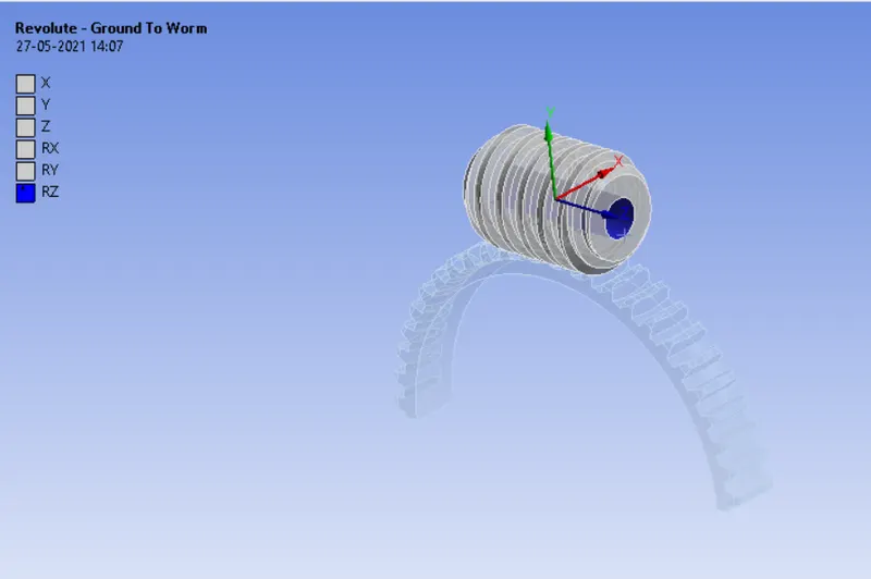
- The two joints are provided as a Revolute (body to the ground) one joint to the gear, selecting the bottom b]face of the gear, and checking the coordinate system as the gear revolutes in the (RZ) Z-direction
- And second joints are provided to the worm selecting the inner face of the worm and checking the coordinate system revolutes in the RZ direction.
Mesh
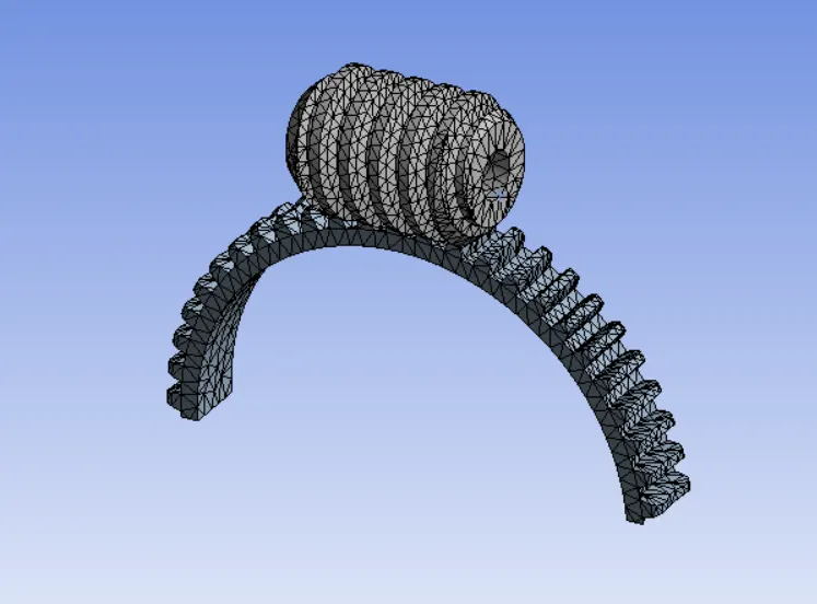
- The worm gear simulation is refined with a 1.5mm mesh size and then generated then mesh, Obtain mesh has nodes below academic limits Nodes - 16348 and elements - 8471.
Analysis Settings
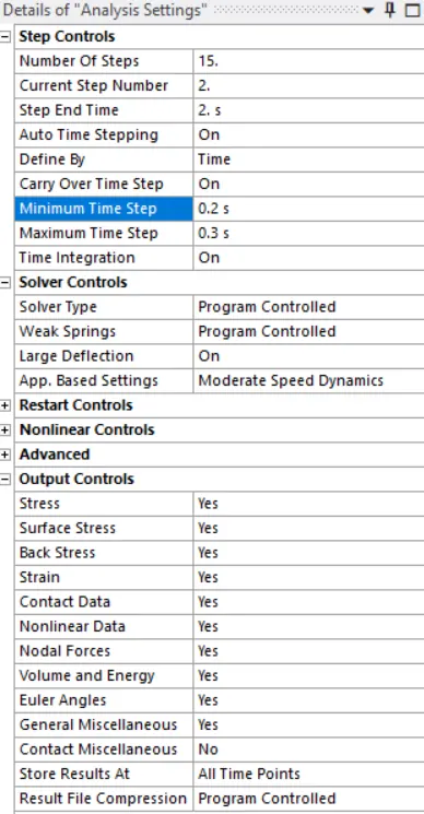
- For setting up the simulation for this setup total of 15 steps are taken for step 1 the time value for initial time setup 0.2s, minimum time 0.2s, and final time step 0.5s. For output, controls switch ON all the parameters except the contact miscellaneous is OFF
- And for steps 2 to 15, keeping the time step ON and also carry over time step is ON with minimum time step is 0.2s and maximum time step 0.5s.
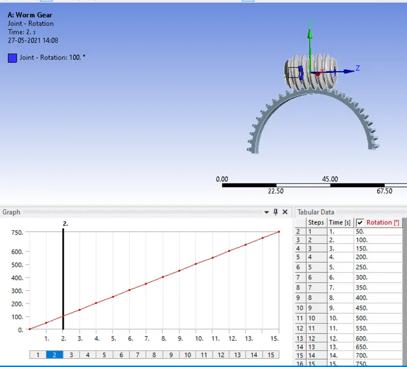
- To rotate the worm on the gear the joint load is given as a rotation (revolute ground to worm) and rotation at 50 degrees at each step.
RESULTS AND CONCLUSION
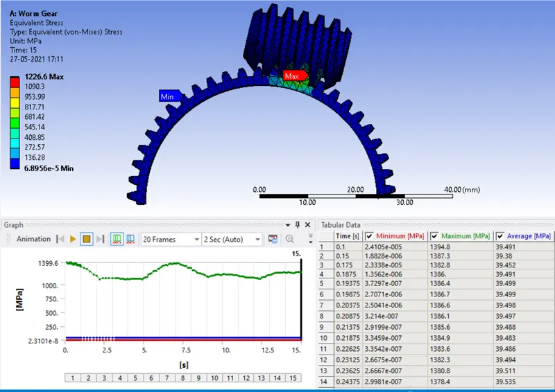
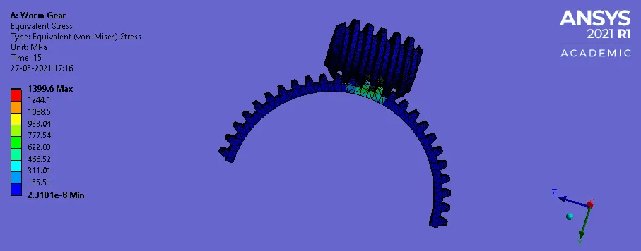
Equivalent von mises stress
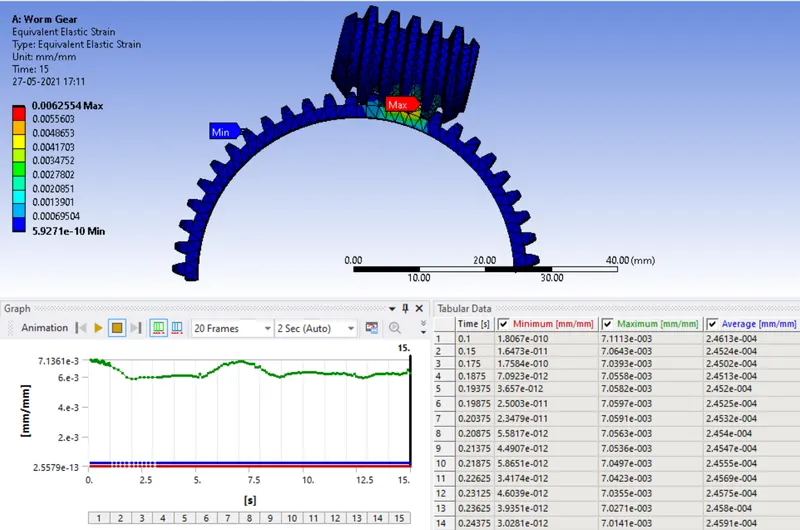
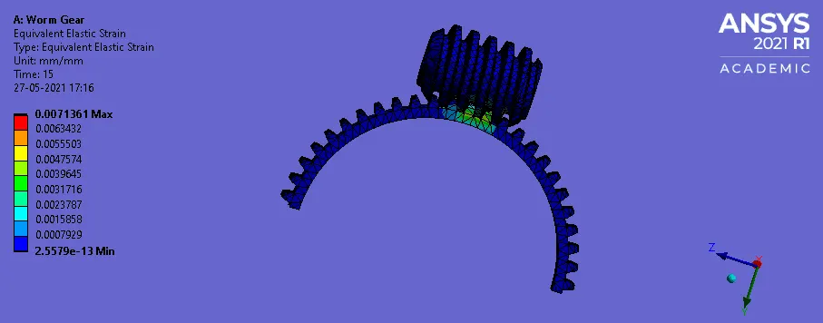
Equivalent elastic strain
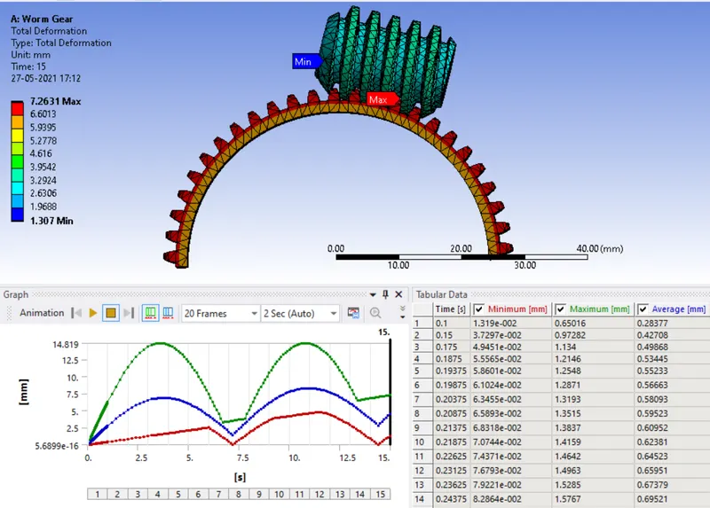
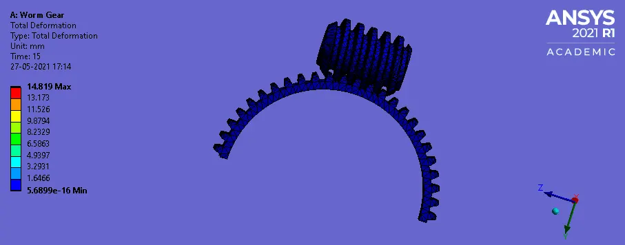
Total Deformation
CONCLUSION:

- Thus the worm gear assembly is simulated with transient structural analysis and the following results are obtained.
- Max. Total deformation = 7.2631mm
- Max. Equivalent Stress= 12266.6 Mpa
- Max .Equivalent Strain = 6.2554e-003 mm/m