Week 8 Worm Gear Challenge
AIM :
To Perform a transient Structural analysis on a worm & worm gear by using ANSYS.
OBJECTIVES :
Adding & Assigning the material to the model.
Create a Contact connection between Worm & worm gear.
Create a Joint Connection for worm and worm gear.
Meshing the model.
Applying the boundary condition to the model.
INTRODUCTION :
A Worm Dirve is a gear arrangement in which a worm ( which is a gear in the form of a screw) meshed with a worm wheel (Which is similat in appearance to a spur gear). The set components are called worm screw & worm gear.
One of the commonly application is belt conveyors.
PROCEDURE FOR ATTAINING THE OBJECTIVES :
I) CAD Model:
A Worm & Worm gear model is given from design team. After importing the CAD file into the ANSYS Space claim, it has to looks like as shown in below image.
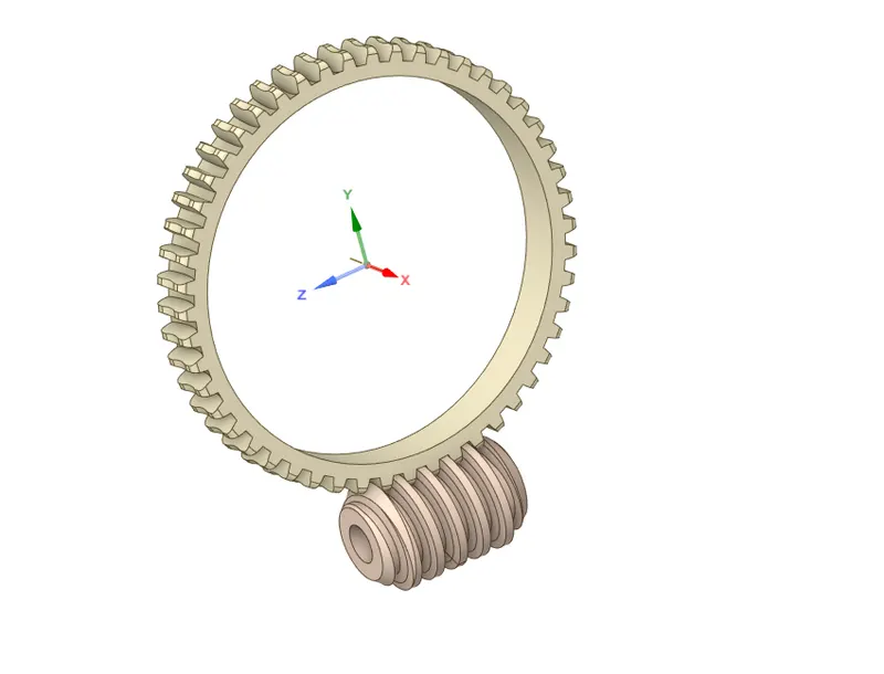
We have to cut into two half for minimizing the computational calculating time & storage space as well.
Choose the plane where we want to make cut, by using XZ plane to cut the model.
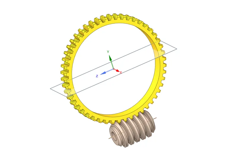
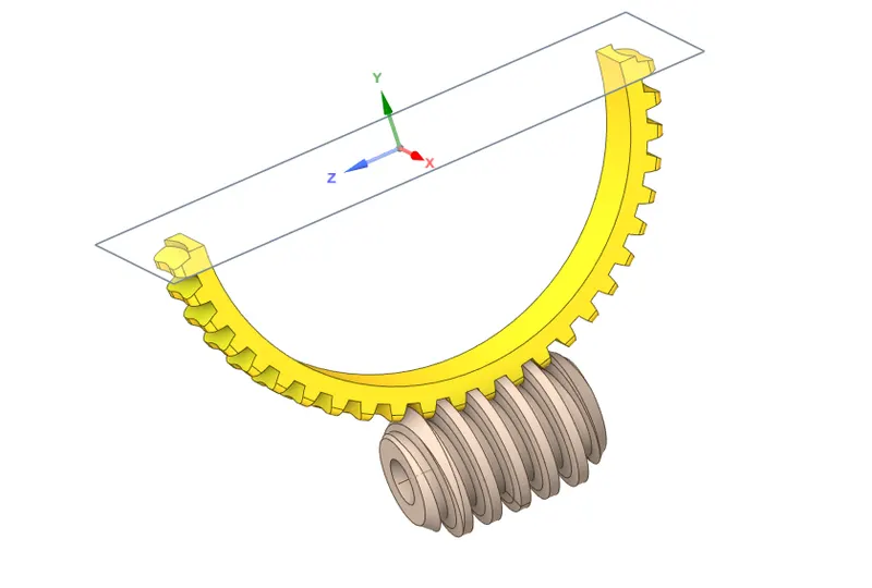
Once, we made a cut across the worm gear. Now, we can simply delete the top portion like as shown in below.
This same model, we gonna use for simulation where in upcoming stage.
II) Adding & Assigning the material :
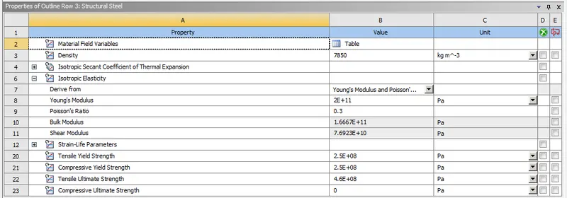
By default, a structural steel material is added in the materials list, so we can use it as a material for worm & worm gear.
III) Connections :
In this setup, we have to create two different connections which are Joint connection & Contact connection.
Contact Connection :
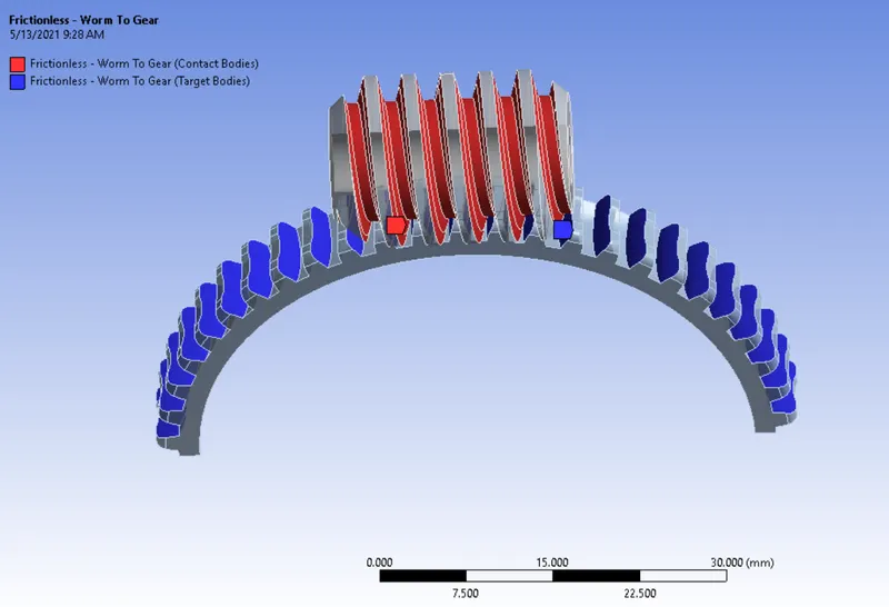
Select the worm contact face as a contact body & select the worm gear contact face as a target body like as shown in below.
Select "Frictionless" as a type of contacts
Keep default settings as it is.
Joint Connections :
Revolute Joint for Worm Gear :
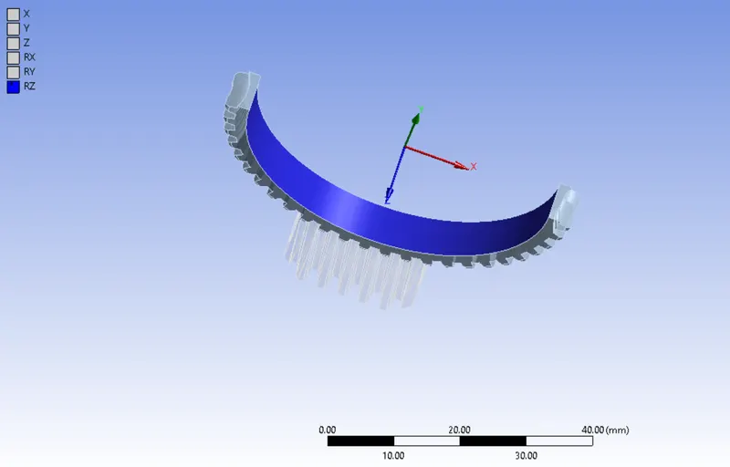
Select the inner face like as shown in below, it will automatically create a coordinate to that.
Now, a worm gear is constrained in all possible degree of freedom except rotational about an Z axis.
Revolute Joint for Worm :
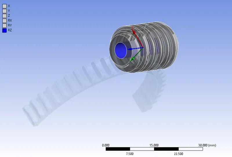
Similarly, select the inner face for worm screw like as shown in below & click to create it.
As usual, a rotation about Z axis is only unconstrained for it.
IV) Meshing :
To Split the geometry into finite number of elements that are connected together with nodes, this process is called discretization and that framework or rather let's say collection of nodes and elements is defined by whole model is called meshing. This Finite element method is widely used for solving partial differential equation in different physical field such as Structural problem, Heat transfer problem, Fluid flow problem, Electro magnetic Analysis & Acoustics Analysis.
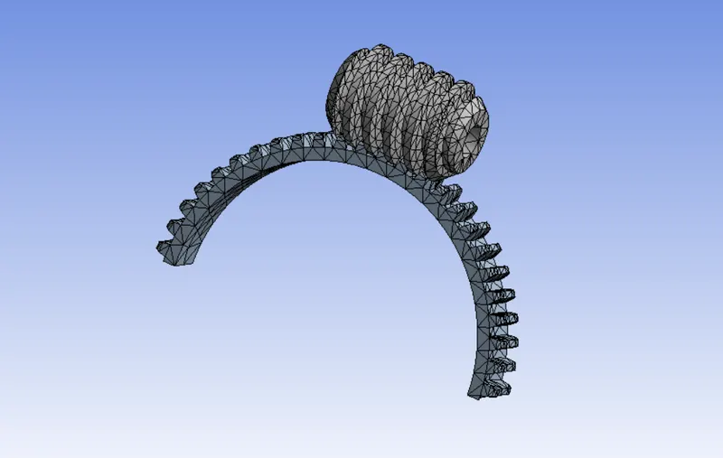
Number of Nodes = 10258
Number of Elements = 5049
A Both worm & worm gear are meshed with tetrahedral elements only.
V) Analysis Settings :
We gonna soving it by 45 number of step.
For first time step,
Initial time step is 0.2 sec
Minimum Time step is 0.2 sec
Maximum Time Step is 0.5 sec
Switch to "Program Controlled" for Weak Spring.
Switch to "ON" for Large Deflection.
Switch to "Yes" for all options except "Contact Miscellaneous" option which are comes below in the "Output controls" setting.
For 2 - 45 time steps,
Switch "ON" for Carry Over time step.
Minimum Time step is 0.2 sec
Maximum Time Step is 0.5 sec
Apart from time steps, keep all options are to be same as which provided in the previous time step.
Boundary Condition :
Rotational Joint :
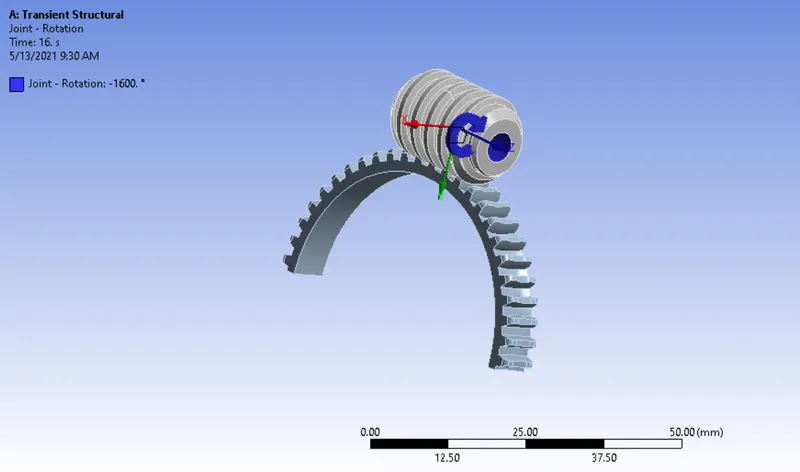
Select "Ground to Worm" for type of joint, followingly select "Rotational" for type of definition.
A Worm will be rotate from 0 degree to 4500 degree with equidistant interval of 45 number of time step, then only worm gear is rotate upto be quarter half.
RESULTS :
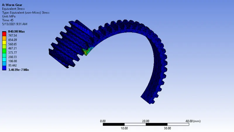
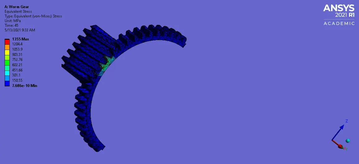
Equivalent Stress :
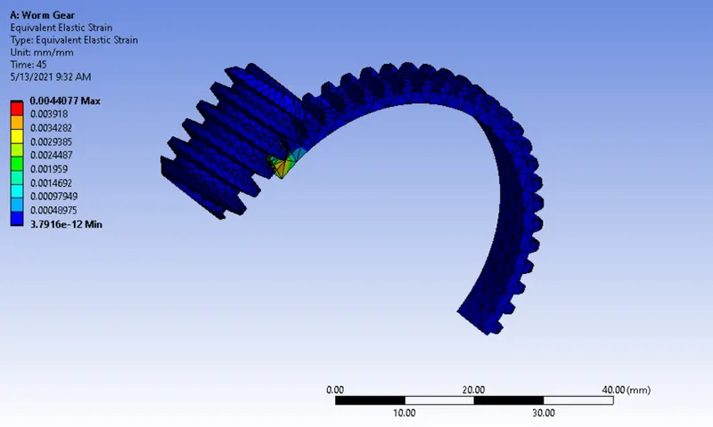
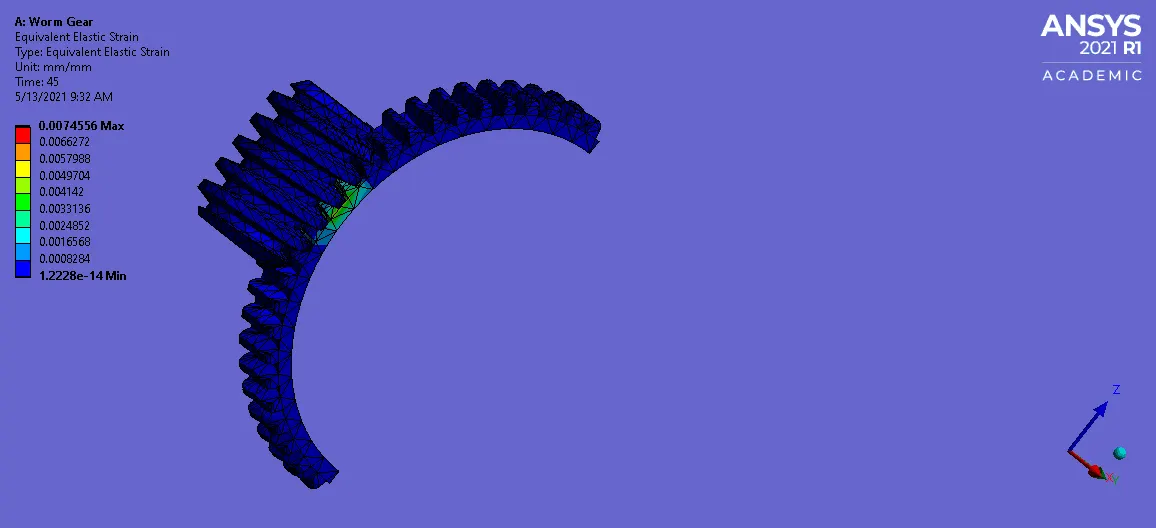
Equivalent Elastic Strain :
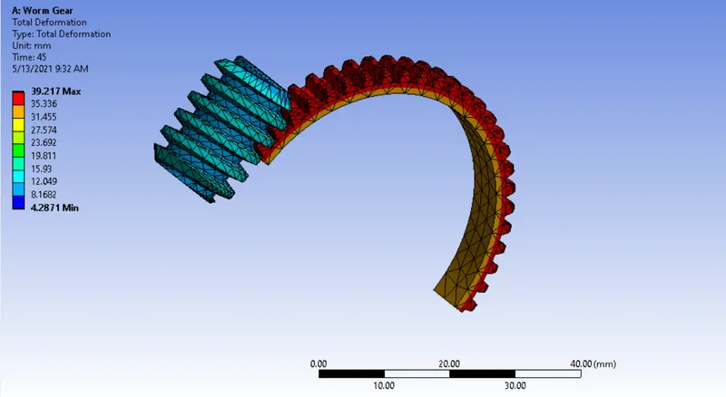
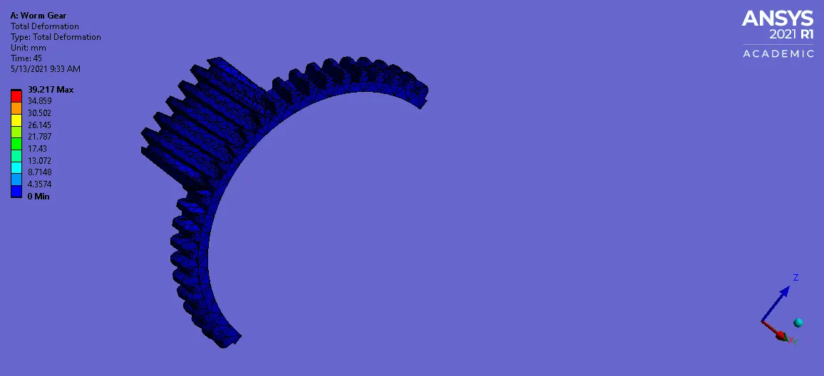
Total Deformation :
CONCLUSION :
A Maximum stress & strain are generated on where gear teeths had been contacted.
A Maximum deformation are happened on the worm gear teeth.
A Worm gear is successfully rotate upto one fourth of complete revolution from the initial location.
Learning Outcome :
I Learnt How to simiplify the problem like cut the worm gear.
And Learnt How to Create joint & contact connection for that.