Week 8 - Universal Joint
AIM :
To Perform a transient structural simulation on a double universal joint with a spring by using ANSYS.
OBJECTIVES :
Adding the materials from the engineering data source.
Assigning the materials to the respective components.
Create a Joint Connections between the components where it's required.
Discretize the whole geometry.
Applying the Boundary condition
INTRODUCTION :
A Universal Joint or Coupling is used to connecting the two shaft whose axes is inclined to each other and it's transmit the rotary motion from one shaft to another shaft. It can able to transmit the rotary motion without any power loss.
It is used to transmit the power from gear box output shaft to Differential Input shaft and Mechanical connections between in the machinery parts too.
PROCEDURE FOR GETTING THE OBJECTIVES :
I) CAD Model :
i) Shaft with Gear :
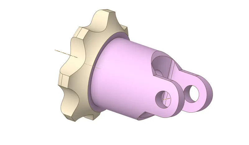
ii) Coupling with Joint :
iii) Shaft with Spring :
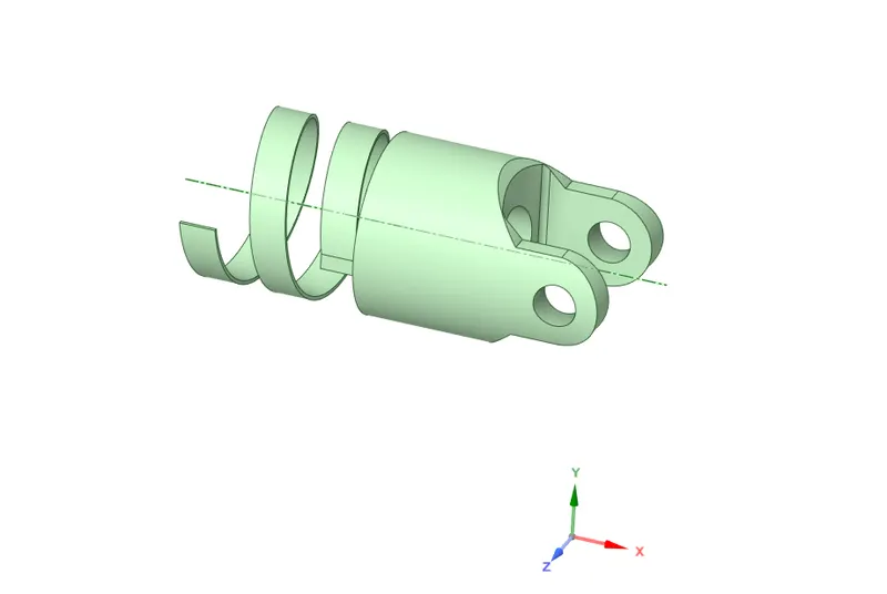
II) Materials Adding & Assigning :
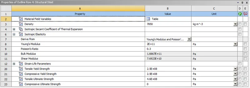
i) Structural Steel :
A Structural steel materials is used for all components which are available as per first case requirement.
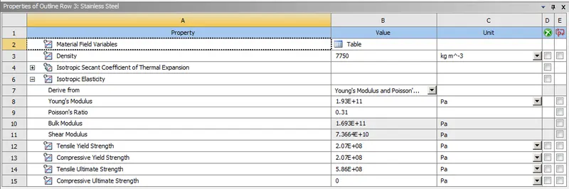
ii) Stainless Steel :
A Stainless Steel material is used for which "shaft with spring" component, apart from that we should be use structural steel material for remaining components.
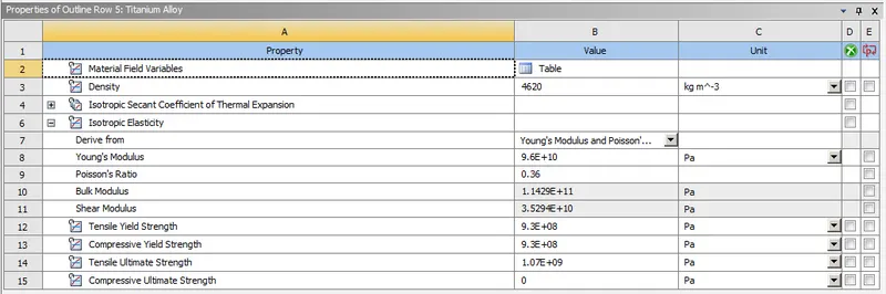
iii) Titanium Alloy :
A Titanium Alloy material is used for which "shaft with spring" component, apart from that we should be use structural steel material for remaining components.
III) Connections :
In this simulation, we have to create a joint connections where it have been rotate by it's own axis & also be transfer the rotational power as well from one shaft to another shaft.
Joint Connections :
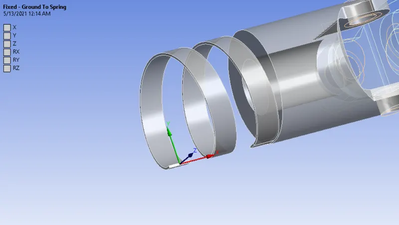
Fixed Joint :
Select the face & fix it by using fixed support like as shown in below image. Now, selected face has been constrained in all possible degree of freedom.
Revolute Joint for Gear shaft :
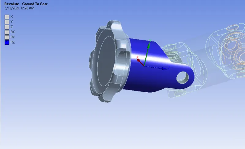
Select "Body to Ground" as a connection type & then followingly choose the "Revolute" as a type of joint.
Select the face properly like as shown in below image. Once we created the revolute joint, a gear shaft is constrained in all possible degree of freedoms except which rotational about an z axis.
Revolute Joint for Spring Shaft :
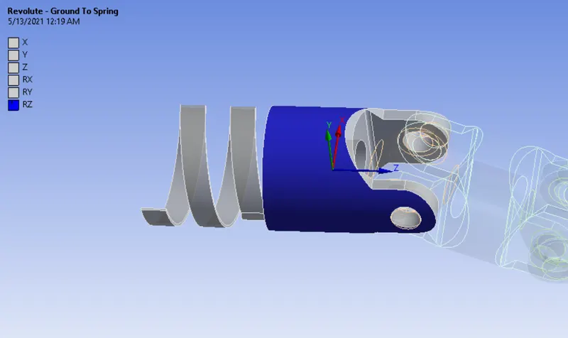
Similarly, we should create a revolute joint for gear spring component as well.
Revolute Joints between Joint to Shaft :
First of all, select "Body to Body" as a type of connection & then followingly choose "Revolute" as a type definition.
Select the inner Face of gear shaft as a Reference body & select the outer face of the solid as a Mobile Body.
Make sure have to check the Z axis coordinate. Now, it would be perfect.
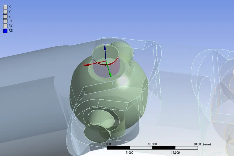
Similarly, have to create a revolute joint on wherever required. After a revolute joints are created at where required region, it's will be looks like as shown in below.
Make sure check the respective coordinate axis for all individual joint.
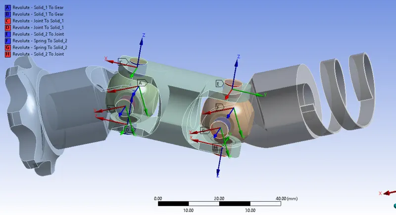
V) Meshing :
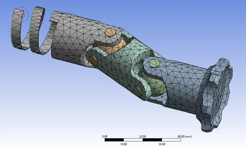
To Split the geometry into finite number of elements that are connected together with nodes, this process is called discretization and that framework or rather let's say collection of nodes and elements is defined by whole model is called meshing. This Finite element method is widely used for solving partial differential equation in different physical field such as Structural problem, Heat transfer problem, Fluid flow problem, Electro magnetic Analysis & Acoustics Analysis.
Element Size is 4 mm
Number of Nodes = 11807
Number of Elements = 6098
All Components are meshed with Tetrahedral Elements.
After meshed, a universal joint has to be look like as shown in below.
V) Analysis Settings :
We have to solving this model upto 6 number of steps.
For first time step,
Switch "OFF" the Auto Time step
Switch to "Program Controlled" for weak spring
Switch to "ON" for Large Deflection.
Time step is 0.1 sec
Keep "Yes" for all options which are comes under the "Output Controls".
For 2 to 6 time step,
Performing with multiple time step
Keep same option as did in previuos time step.
Boundary Condition :
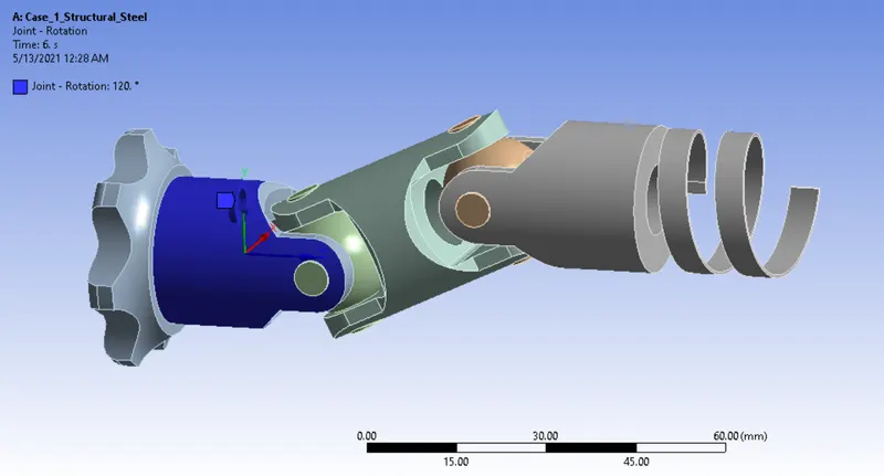
Rotation Joint :
Select the "Ground to Gear Shaft" as a type of joint, followingly select "Rotational" for type of definition.
A Gear shaft will be rotate from 0 degree to 120 degree with 20 degree interval or equidistant interval of six number of time step.
RESULTS :
CASE 1 :
Equivalent Stress :
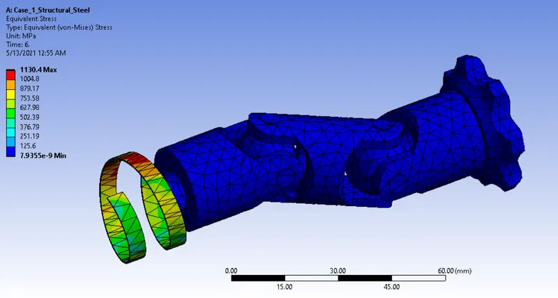
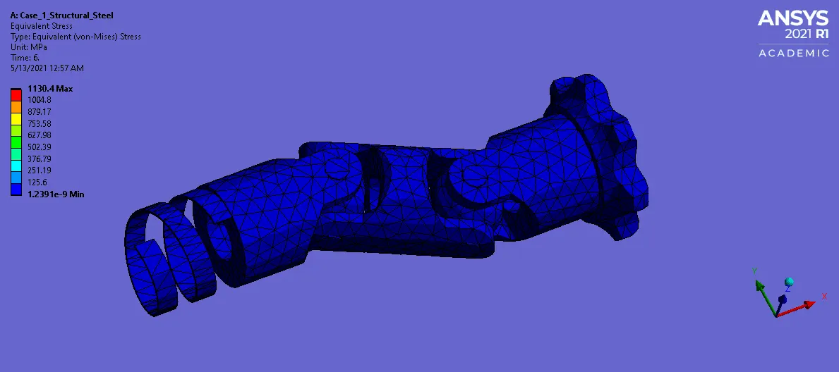
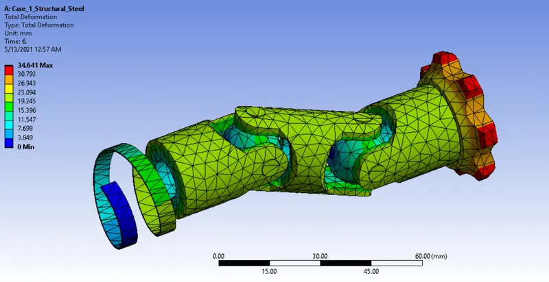
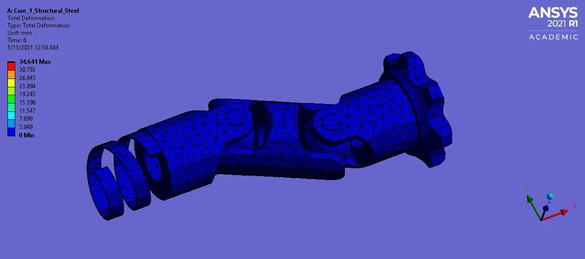
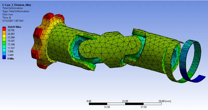
Total Deformation :
CASE 2 :
Equivalent Stress :
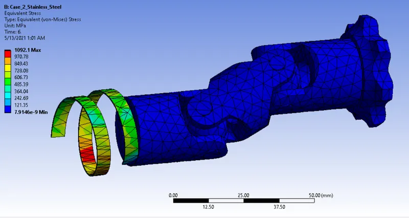
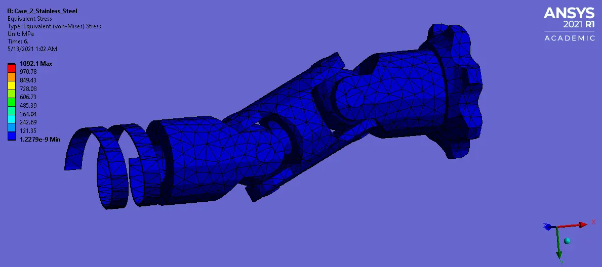
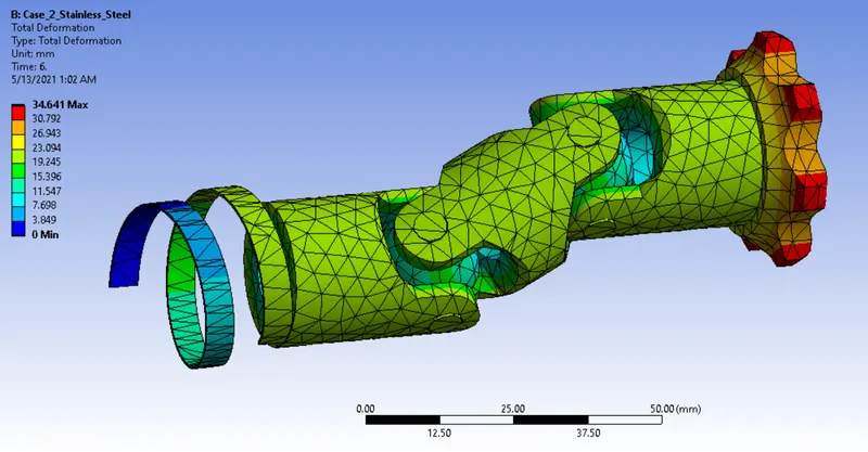
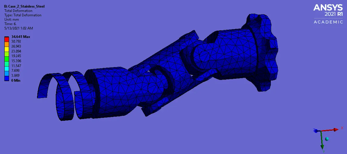
Total Deformation :
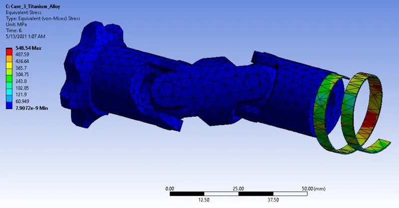
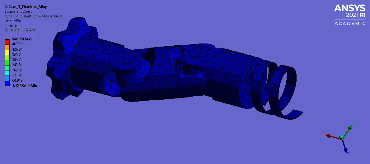
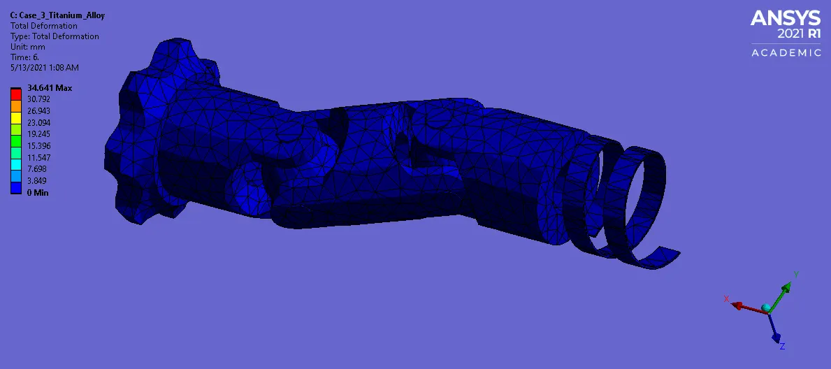
CASE 3:
Equivalent Stress :
Total Deformation :
CONCLUSION :
| Cases\Variables | Material Used for Spring | Equivalent Stress in Mpa | Total Deformation in mm |
| Case 1 | Structural Steel | 1130.4 | 34.641 |
| Case 2 | Stainless Steel | 1092.1 | 34.641 |
| Case 3 | Titanium Steel | 584.54 | 34.641 |
A Maximum Stress is developed on the spring, it has been varied based on respective material to material. For Structural Steel material, a maximum stress is high as compared than other two materials Which means, it have more respective force. So, we preferred Structural steel as a material for spring.
A Total Deformation is equal to all three cases, a maximum deformation were generated on outer most region of the gear.
Learning Outcome :
I Learnt How to create a Joint connection with proper definition of Mobile & Reference Body.