Week 8 - Universal Joint
UNIVERSAL JOINT SIMULATION
OBJECTIVE
To perform a simulation involving components connected with a universal joint such that they transmit revolute motion when applied to one component. The simulation is performed in 3 different cases - with structural steel, stainless steel and titanium alloy for the component with the spring.
INTRODUCTION
A universal joint or 'u' joint is a coupling that connects two shafts that are at different angles to one another such that it allows both to rotate freely without excess friction
EX: U-joints can be located along driveshafts, 4WD transfer case shafts, and even axle shafts.
PROCEDURE
- Create a new transient structural simulation
- Import structural steel, stainless steel and titanium alloy from general materials as the desired material for all the components
- Import the geometry file onto the Spaceclaim GUI
- Then the model module of static structural is again updated.
- Open the model in ansys mechanical module.
Material assignment
The structural steel is added to all the three components.
In the next two cases stainless steel and titanium alloy are added to the spring component.
Joint and Joint load
The spring is fixed at space using a body-to-ground fixed joint
Eight revolute body-to-body joints are created for the universal joint and the shaft it is connected to. The joint is kept as the reference and the safts are movable.
A revolute joint with referece to the ground is created to the first component and a joint load of revolute motion about the z axis is set for it
Mesh
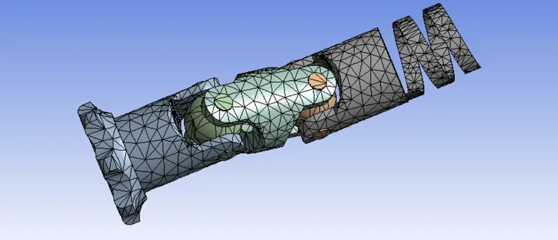
The default mesh size which i based on the geometry is used

Analysis settings
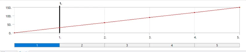
A total of 5 steps are performed with the angle of rotation in the revolute joint increments to about 30deg at each time step
The step size is set to 0.1. However if a solution involving any case fails to converge, then the min and max step size can be reduced to 0.05 and 0.5 respectively (with carry over time step since multi-time steps)
Large deflection = on
Direct/Iterative solver - program-controlled.
Weak springs - program-controlled.
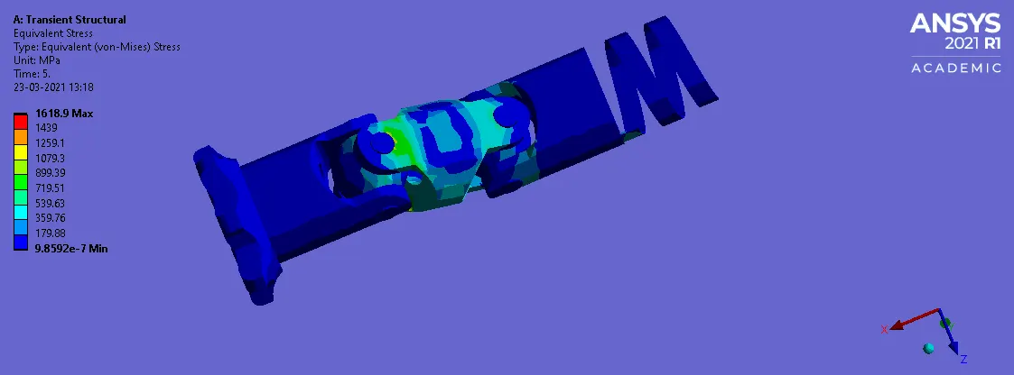
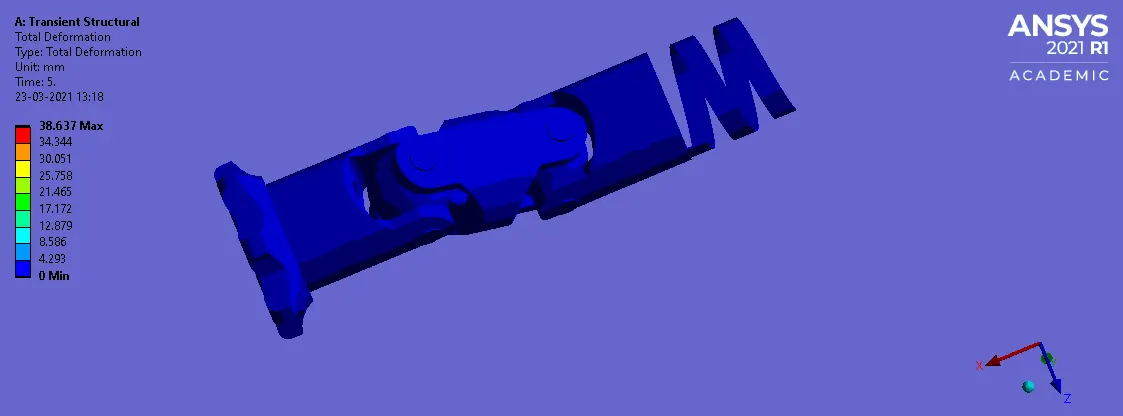
RESULTS
CASE 1
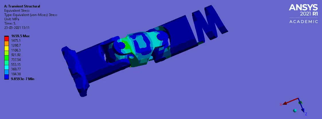
Equivalent stress
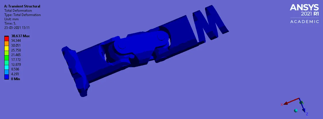
Total Deformation
CASE 2
Equivalent stress
Total Deformation
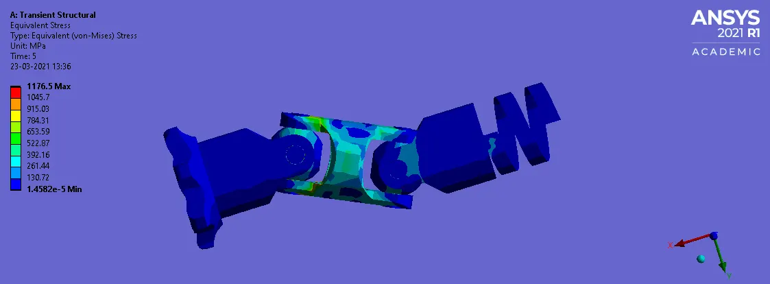
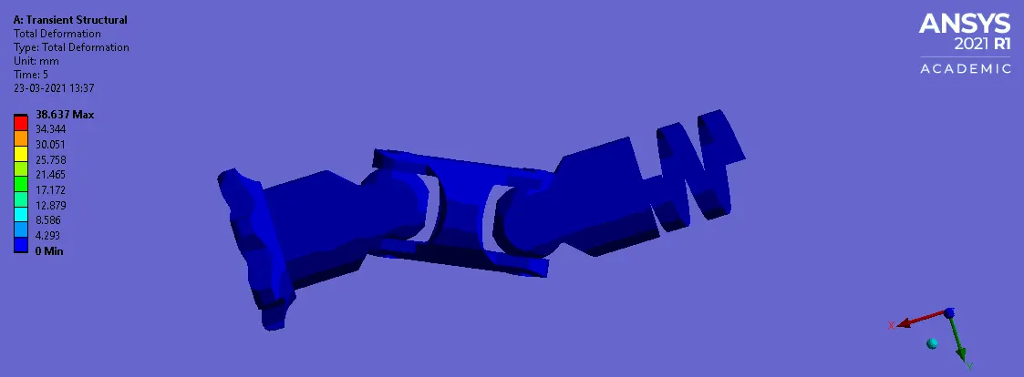
CASE 3
Equivalent stress
Total Deformation
CONCLUSION
Hence from the above results, we can conclude that there is no significant difference between case 1 and 2, however a huge difference in the stress value for case 3. This is due to the fact that the young's modulus of titanium alloy is significantly lower than compared to structural or stainless steel and a small change contributed because of the reduced time step to force the model to converge. However, the total deformation experienced in the system is same in all three cases since the loading conditions doesn't vary.