Week 8 - Simulation of a backward facing step in OpenFOAM
Week 8 - Simulation of a backward-facing step in OpenFOAM
AIM:
This challenge is to simulate an incompressible-laminar-viscous flow through the backward-facing step geometry. Also should perform a transient simulation. The solver can be chosen based on the described physics of the flow. It needs to explain the entire simulation procedure (how we set up the case). This challenge should also provide explanations for every change we make inside the reference case files obtained from OpenFOAM tutorials. We can choose the inlet velocity such that the flow is laminar.
After that, you will perform 2 case studies as described below and compare the results.
Case 1 - Simulate the flow without using any grading factor (i.e., GF = 1)
Case 2 - Simulate the flow with a grading factor of 0.2. The cells should be finer near the walls (including the step wall).
You can use the following mesh parameters but you can feel free to modify these values.
Mesh specification
- Number of cells along the x direction (longer dimension) = 200
- Number of cells along the longer y direction = 20;
Boundary condition specification
The domain specifications are provided in the following figure.
Desired output
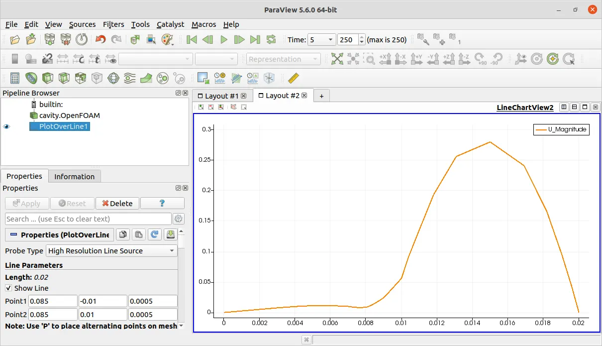
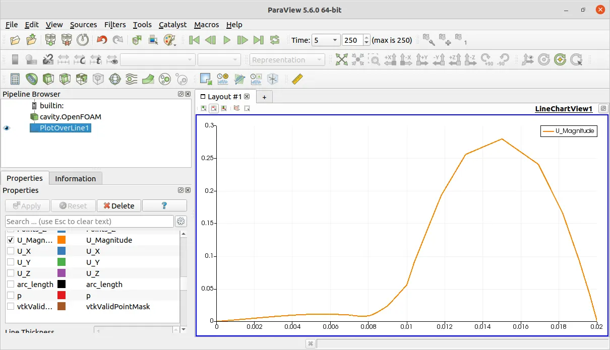
- Measure the velocity profile at 0.085 m from the inlet of the geometry for both case studies and compare. You can use the plot over line tool for this.
- Explain why the Grading/Growth factor is essential for meshing.
Primary setup
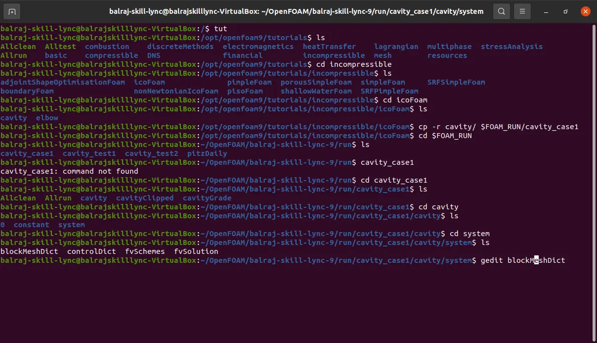
- Open a new CMD/Powershell terminal
- Write the codes like tut - tutorial
- Check the Files and Folder in tutorial by typing the code - ls
- Chose the Folder Incompressible by typing the code - cd incompressible
- Chose the Folder IcoFoam by typing the code - cd icoFoam
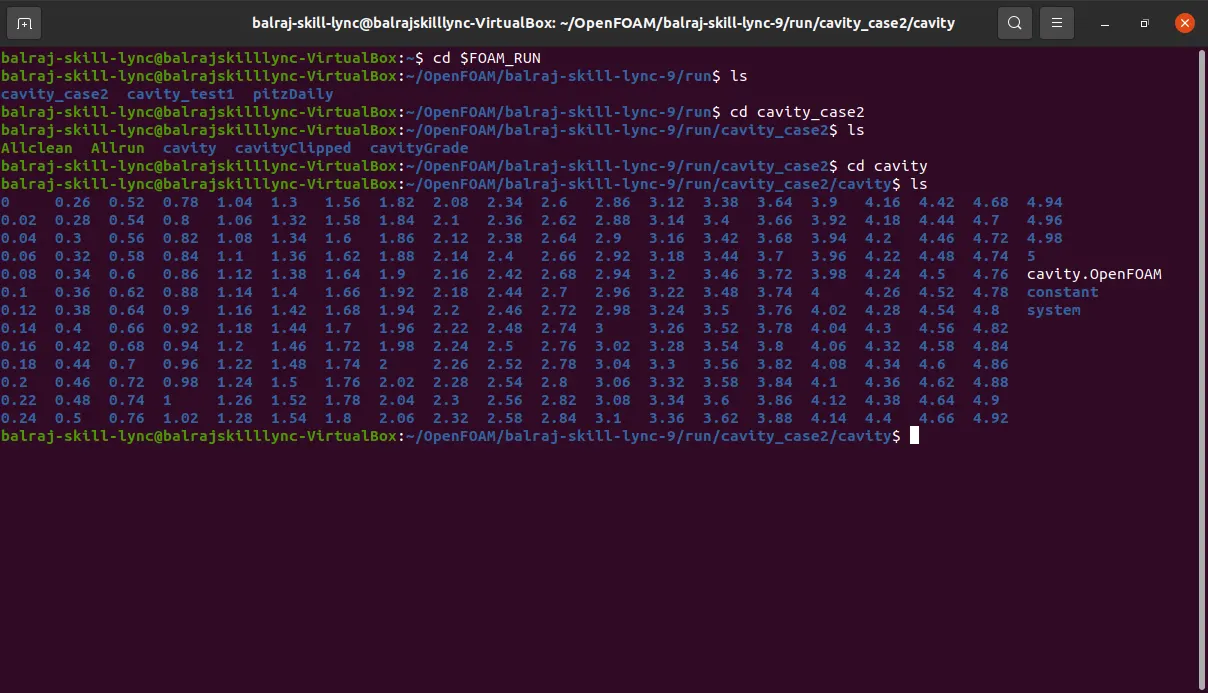
- Copy the cavity folder to run folder
- By typing the code - cp -r cavity/ $FOAM_RUN/cavity_case1
- After copying check the folder in run folder bychecking by using the code - cd $FOAM_RUN
- Open fun folder by using this code- cd |$FOAM_RUN
- Check for the folder cavity_case1
Case 1 : Simulating the flow without using any grading factor (i.e., GF = 1)
- Once copied the Folder cavity_case1 open the folder by using this code- cd cavity_case1
- Open th folder cavity by using this code - cd cavity
- open the folder system by using this code - cd system
- Edit the file blockmeshdict by using this code - gedit blockMeshDict
- make changes in this file like this.
blockMeshDict:
- This file defines the mesh geometry for a simulation in OpenFOAM.
- It specifies block topology, block sizes, boundary conditions, and other mesh generation parameters.
- Users define the mesh by specifying vertices, blocks, edges, faces, and boundary patches.
/*--------------------------------*- C++ -*----------------------------------*\
  =========                 |
  \\      /  F ield         | OpenFOAM: The Open Source CFD Toolbox
   \\    /   O peration     | Website:  https://openfoam.org
    \\  /    A nd           | Version:  9
     \\/     M anipulation  |
\*---------------------------------------------------------------------------*/
FoamFile
{
    format      ascii;
    class       dictionary;
    object      blockMeshDict;
}
// * * * * * * * * * * * * * * * * * * * * * * * * * * * * * * * * * * * * * //

convertToMeters 1;

vertices
(
    // vertices from point 0 to 10
    (0 0 0)
    (0.08 0 0)
    (0.08 0.005 0)
    (0 0.005 0)
    (0.08 0.01 0)
    (0 0.01 0)
    (0.2 0.01 0)
    (0.2 0.005 0)
    (0.2 0 0)
    (0.2 -0.01 0)
    (0.08 -0.01 0)

    // vertices from point 11 to 21
    (0 0 0.1)
    (0.08 0 0.1)
    (0.08 0.005 0.1)
    (0 0.005 0.1)
    (0.08 0.01 0.1)
    (0 0.01 0.1)
    (0.2 0.01 0.1)
    (0.2 0.005 0.1)
    (0.2 0 0.1)
    (0.2 -0.01 0.1)
    (0.08 -0.01 0.1)
);

blocks
(
// block 1
hex (0 1 2 3 11 12 13 14) (80 5 1) simpleGrading (0.2 5 1)
//block 2
hex (3 2 4 5 14 13 15 16) (80 5 1) simpleGrading (0.2 0.2 1)
//block 3
hex (2 7 6 4 13 18 17 15) (120 5 1) simpleGrading (5 0.2 1)
//block 4
hex (1 8 7 2 12 19 18 13) (120 5 1) simpleGrading (5 5 1)
//block 5
hex (10 9 8 1 21 20 19 12) (120 10 1) simpleGrading (5 1 1)
);

edges
(
);

boundary
(
    inlet
    {
        type patch;
        faces
        (
            (11 14 3 0)
            (14 16 5 3)
        );
    }
    outlet
    {
        type patch;
        faces
        (
            (6 17 18 7)
            (8 7 18 19)
            (9 8 19 20)
        );
    }

    otherwall  //no slip walls
    { type wall;
        faces
        (
        //top
            (15 4 5 16)
            (15 17 6 4)
            //step
            (21 12 1 10)
            //bottom left
            (11 0 1 12)
            //bottom right
            (21 10 9 20)
        );
    }
    frontAndBack
    {
        type empty;
        faces
        ( //back
            (0 3 2 1)
            (3 5 4 2)
            (2 4 6 7)
            (1 2 7 8)
            (10 1 8 9)
            //front
            (13 15 16 14)
            (12 13 14 11)
            (20 19 12 21)
            (19 18 13 12)
            (18 17 15 13)
        );
    }
);
mergePatchPairs
(
);
// ************************************************************************* //- Again open the file contolDict by using this code - gedit controlDict
ControlDict:
- controlDict is the main control file in OpenFOAM, governing the execution of the simulation.
- It specifies time settings, solver settings, output control, and other simulation parameters.
- Users can define start and end times, time steps, solver settings (e.g., tolerances), and output formats.
/*--------------------------------*- C++ -*----------------------------------*\
  =========                 |
  \\      /  F ield         | OpenFOAM: The Open Source CFD Toolbox
   \\    /   O peration     | Website:  https://openfoam.org
    \\  /    A nd           | Version:  9
     \\/     M anipulation  |
\*---------------------------------------------------------------------------*/
FoamFile
{
    format      ascii;
    class       dictionary;
    location    "system";
    object      controlDict;
}
// * * * * * * * * * * * * * * * * * * * * * * * * * * * * * * * * * * * * * //

application     icoFoam;

startFrom       startTime;

startTime       0;

stopAt          endTime;

endTime         5;

deltaT          0.001;

writeControl    timeStep;

writeInterval   20;

purgeWrite      0;

writeFormat     ascii;

writePrecision  6;

writeCompression off;

timeFormat      general;

timePrecision   6;

runTimeModifiable true;

//adaptive timestep
/*
adjustTimeStep true;

maxCo 1;*/- return to the previous folder by using the code - cd ..
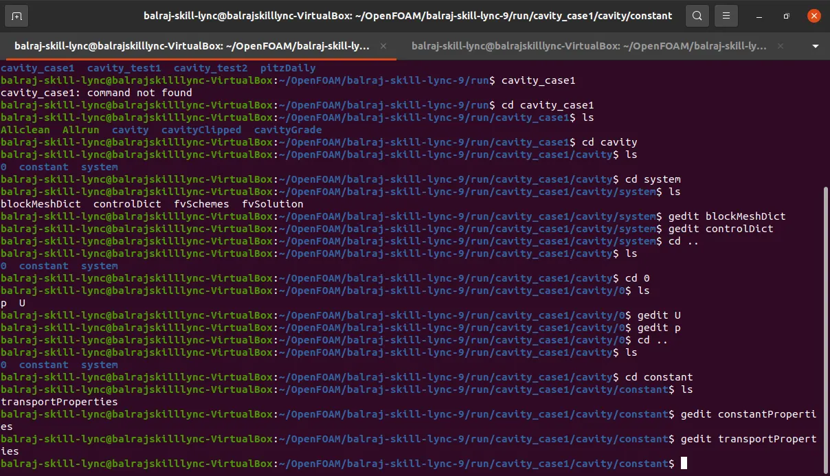
- select the folder 0 by using this code - cd 0
- Edit the file name U and p using the similar code - -gedit U, gedit p
U : Represents the velocity field in OpenFOAM.
- It is a vector field defining velocity components (typically u, v, w) at each mesh point.
- Solved using solvers like simpleFoam, pisoFoam, etc., depending on the type of flow.
/*--------------------------------*- C++ -*----------------------------------*\
  =========                 |
  \\      /  F ield         | OpenFOAM: The Open Source CFD Toolbox
   \\    /   O peration     | Website:  https://openfoam.org
    \\  /    A nd           | Version:  9
     \\/     M anipulation  |
\*---------------------------------------------------------------------------*/
FoamFile
{
    format      ascii;
    class       volVectorField;
    object      U;
}
// * * * * * * * * * * * * * * * * * * * * * * * * * * * * * * * * * * * * * //

dimensions      [0 1 -1 0 0 0 0];

internalField   uniform (0.1 0 0);

boundaryField
{
    inlet
    {
        type            fixedValue;
        value           uniform (0.2 0 0);
    }

    outlet
    {
        type            zeroGradient;
    }

    frontAndBack
    {
        type            empty;
    }
    otherwall
    {
    	type 		noSlip; // zero at walls
    }
}
p : Represents the pressure field in OpenFOAM.
- It is a scalar field representing pressure at each mesh point.
- Solvers like simpleFoam, pisoFoam, etc., solve for pressure to enforce continuity in the flow field.
/*--------------------------------*- C++ -*----------------------------------*\
  =========                 |
  \\      /  F ield         | OpenFOAM: The Open Source CFD Toolbox
   \\    /   O peration     | Website:  https://openfoam.org
    \\  /    A nd           | Version:  9
     \\/     M anipulation  |
\*---------------------------------------------------------------------------*/
FoamFile
{
    format      ascii;
    class       volScalarField;
    object      p;
}
// * * * * * * * * * * * * * * * * * * * * * * * * * * * * * * * * * * * * * //

dimensions      [0 2 -2 0 0 0 0];

internalField   uniform 0;

boundaryField
{
    inlet
    {
        type            zeroGradient;
    }

    outlet
    {
        type            fixedValue;
        value		uniform 0;
    }

    frontAndBack
    {
        type            empty;
    }
    otherwall
    {
    	type 		zeroGradient;
    }
}
transportProperties:
- This file contains specifications for fluid transport properties such as viscosity, density, and turbulence models.
- Users define properties like kinematic viscosity, turbulent viscosity, and fluid density.
- Additionally, it can include specifications for turbulence models such as k-epsilon or k-omega.
/*--------------------------------*- C++ -*----------------------------------*\
  =========                 |
  \\      /  F ield         | OpenFOAM: The Open Source CFD Toolbox
   \\    /   O peration     | Website:  https://openfoam.org
    \\  /    A nd           | Version:  9
     \\/     M anipulation  |
\*---------------------------------------------------------------------------*/
FoamFile
{
    format      ascii;
    class       dictionary;
    location    "constant";
    object      transportProperties;
}
// * * * * * * * * * * * * * * * * * * * * * * * * * * * * * * * * * * * * * //

nu              [0 2 -1 0 0 0 0] 1e-5;


// ************************************************************************* //
Result:
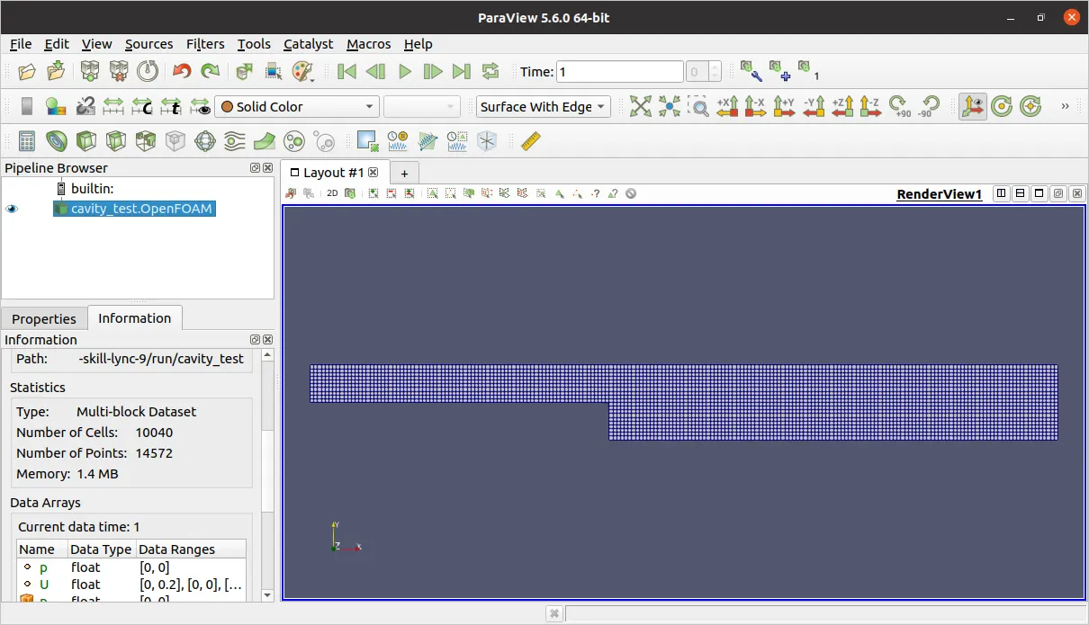
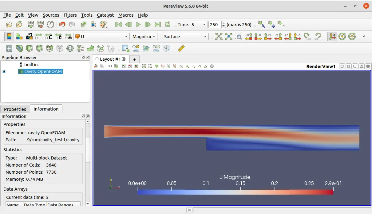
Mesh Grid
velocity
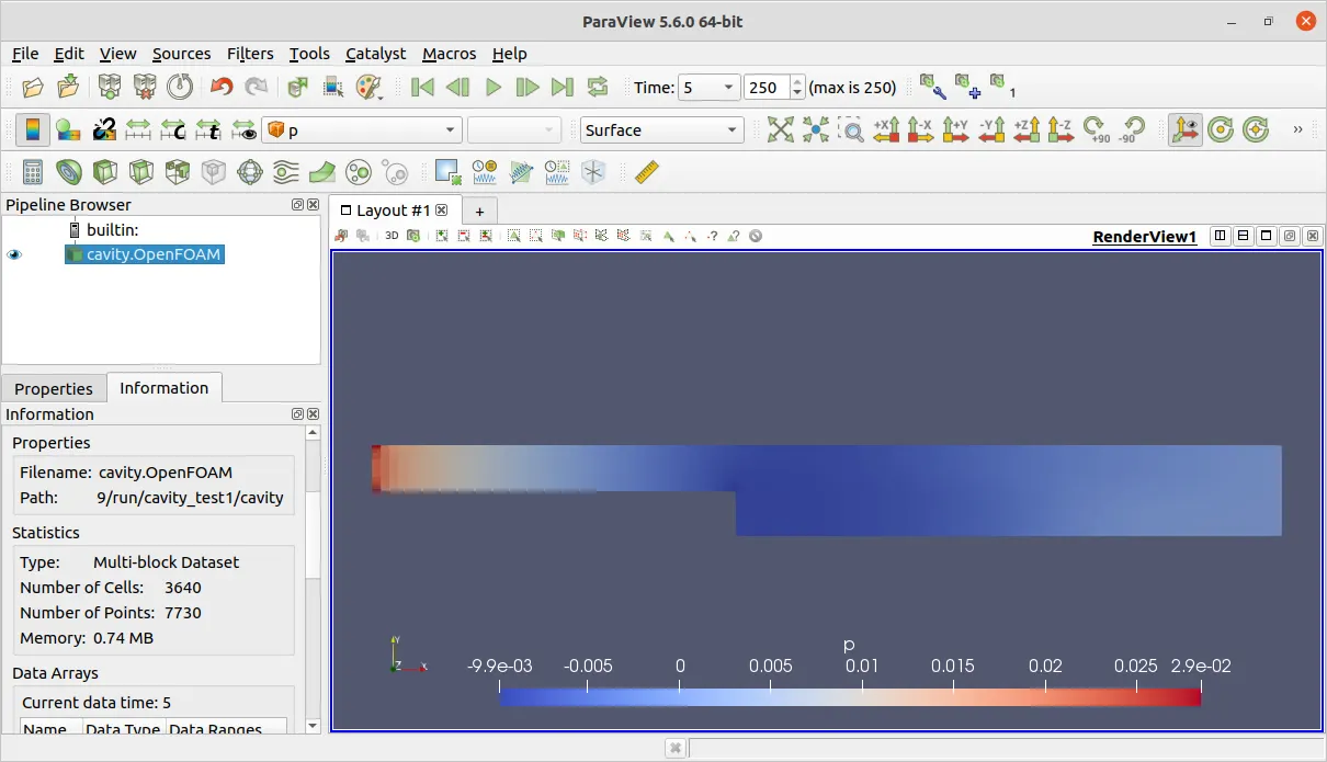
Pressure
Velocity Profile Gif
Velocity Profile at x= 0.085
Case2: Simulate the flow with grading factor of 0.2.
blockMeshDict
/*--------------------------------*- C++ -*----------------------------------*\
  =========                 |
  \\      /  F ield         | OpenFOAM: The Open Source CFD Toolbox
   \\    /   O peration     | Website:  https://openfoam.org
    \\  /    A nd           | Version:  9
     \\/     M anipulation  |
\*---------------------------------------------------------------------------*/
FoamFile
{
    format      ascii;
    class       dictionary;
    object      blockMeshDict;
}
// * * * * * * * * * * * * * * * * * * * * * * * * * * * * * * * * * * * * * //

convertToMeters 1;

vertices
(
    // vertices from point 0 to 10
    (0 0 0)
    (0.08 0 0)
    (0.08 0.005 0)
    (0 0.005 0)
    (0.08 0.01 0)
    (0 0.01 0)
    (0.2 0.01 0)
    (0.2 0.005 0)
    (0.2 0 0)
    (0.2 -0.01 0)
    (0.08 -0.01 0)

    // vertices from point 11 to 21
    (0 0 0.1)
    (0.08 0 0.1)
    (0.08 0.005 0.1)
    (0 0.005 0.1)
    (0.08 0.01 0.1)
    (0 0.01 0.1)
    (0.2 0.01 0.1)
    (0.2 0.005 0.1)
    (0.2 0 0.1)
    (0.2 -0.01 0.1)
    (0.08 -0.01 0.1)
);

blocks
(
// block 1
hex (0 1 2 3 11 12 13 14) (80 5 1) simpleGrading (0.2 5 1)
//block 2
hex (3 2 4 5 14 13 15 16) (80 5 1) simpleGrading (0.2 0.2 1)
//block 3
hex (2 7 6 4 13 18 17 15) (120 5 1) simpleGrading (5 0.2 1)
//block 4
hex (1 8 7 2 12 19 18 13) (120 5 1) simpleGrading (5 5 1)
//block 5
hex (10 9 8 1 21 20 19 12) (120 10 1) simpleGrading (5 1 1)
);

edges
(
);

boundary
(
    inlet
    {
        type patch;
        faces
        (
            (11 14 3 0)
            (14 16 5 3)
        );
    }
    outlet
    {
        type patch;
        faces
        (
            (6 17 18 7)
            (8 7 18 19)
            (9 8 19 20)
        );
    }

    otherwall  //no slip walls
    { type wall;
        faces
        (
        //top
            (15 4 5 16)
            (15 17 6 4)
            //step
            (21 12 1 10)
            //bottom left
            (11 0 1 12)
            //bottom right
            (21 10 9 20)
        );
    }
    frontAndBack
    {
        type empty;
        faces
        ( //back
            (0 3 2 1)
            (3 5 4 2)
            (2 4 6 7)
            (1 2 7 8)
            (10 1 8 9)
            //front
            (13 15 16 14)
            (12 13 14 11)
            (20 19 12 21)
            (19 18 13 12)
            (18 17 15 13)
        );
    }
);
mergePatchPairs
(
);

// ************************************************************************* //
controlDict
/*--------------------------------*- C++ -*----------------------------------*\
  =========                 |
  \\      /  F ield         | OpenFOAM: The Open Source CFD Toolbox
   \\    /   O peration     | Website:  https://openfoam.org
    \\  /    A nd           | Version:  9
     \\/     M anipulation  |
\*---------------------------------------------------------------------------*/
FoamFile
{
    format      ascii;
    class       dictionary;
    location    "system";
    object      controlDict;
}
// * * * * * * * * * * * * * * * * * * * * * * * * * * * * * * * * * * * * * //

application     icoFoam;

startFrom       startTime;

startTime       0;

stopAt          endTime;

endTime         5;

deltaT          0.001;

writeControl    timeStep;

writeInterval   20;

purgeWrite      0;

writeFormat     ascii;

writePrecision  6;

writeCompression off;

timeFormat      general;

timePrecision   6;

runTimeModifiable true;

//adaptive timestep
/*
adjustTimeStep true;

maxCo 1;*/


// ************************************************************************* //
velocity: U
/*--------------------------------*- C++ -*----------------------------------*\
  =========                 |
  \\      /  F ield         | OpenFOAM: The Open Source CFD Toolbox
   \\    /   O peration     | Website:  https://openfoam.org
    \\  /    A nd           | Version:  9
     \\/     M anipulation  |
\*---------------------------------------------------------------------------*/
FoamFile
{
    format      ascii;
    class       volVectorField;
    object      U;
}
// * * * * * * * * * * * * * * * * * * * * * * * * * * * * * * * * * * * * * //

dimensions      [0 1 -1 0 0 0 0];

internalField   uniform (0.1 0 0);

boundaryField
{
    inlet
    {
        type            fixedValue;
        value           uniform (0.2 0 0);
    }

    outlet
    {
        type            zeroGradient;
    }

    frontAndBack
    {
        type            empty;
    }
    otherwall
    {
    	type 		noSlip; // zero at walls
    }
}

// ************************************************************************* //
Pressure: p
/*--------------------------------*- C++ -*----------------------------------*\
  =========                 |
  \\      /  F ield         | OpenFOAM: The Open Source CFD Toolbox
   \\    /   O peration     | Website:  https://openfoam.org
    \\  /    A nd           | Version:  9
     \\/     M anipulation  |
\*---------------------------------------------------------------------------*/
FoamFile
{
    format      ascii;
    class       volScalarField;
    object      p;
}
// * * * * * * * * * * * * * * * * * * * * * * * * * * * * * * * * * * * * * //

dimensions      [0 2 -2 0 0 0 0];

internalField   uniform 0;

boundaryField
{
    inlet
    {
        type            zeroGradient;
    }

    outlet
    {
        type            fixedValue;
        value		uniform 0;
    }

    frontAndBack
    {
        type            empty;
    }
    otherwall
    {
    	type 		zeroGradient;
    }
}
// ************************************************************************* //
transportProperties
/*--------------------------------*- C++ -*----------------------------------*\
  =========                 |
  \\      /  F ield         | OpenFOAM: The Open Source CFD Toolbox
   \\    /   O peration     | Website:  https://openfoam.org
    \\  /    A nd           | Version:  9
     \\/     M anipulation  |
\*---------------------------------------------------------------------------*/
FoamFile
{
    format      ascii;
    class       dictionary;
    location    "constant";
    object      transportProperties;
}
// * * * * * * * * * * * * * * * * * * * * * * * * * * * * * * * * * * * * * //

nu              [0 2 -1 0 0 0 0] 1e-5;


// ************************************************************************* //
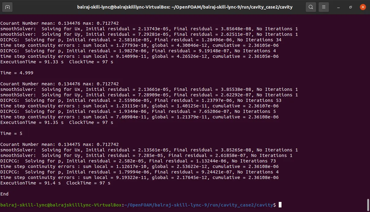
Result:
Mesh Grid
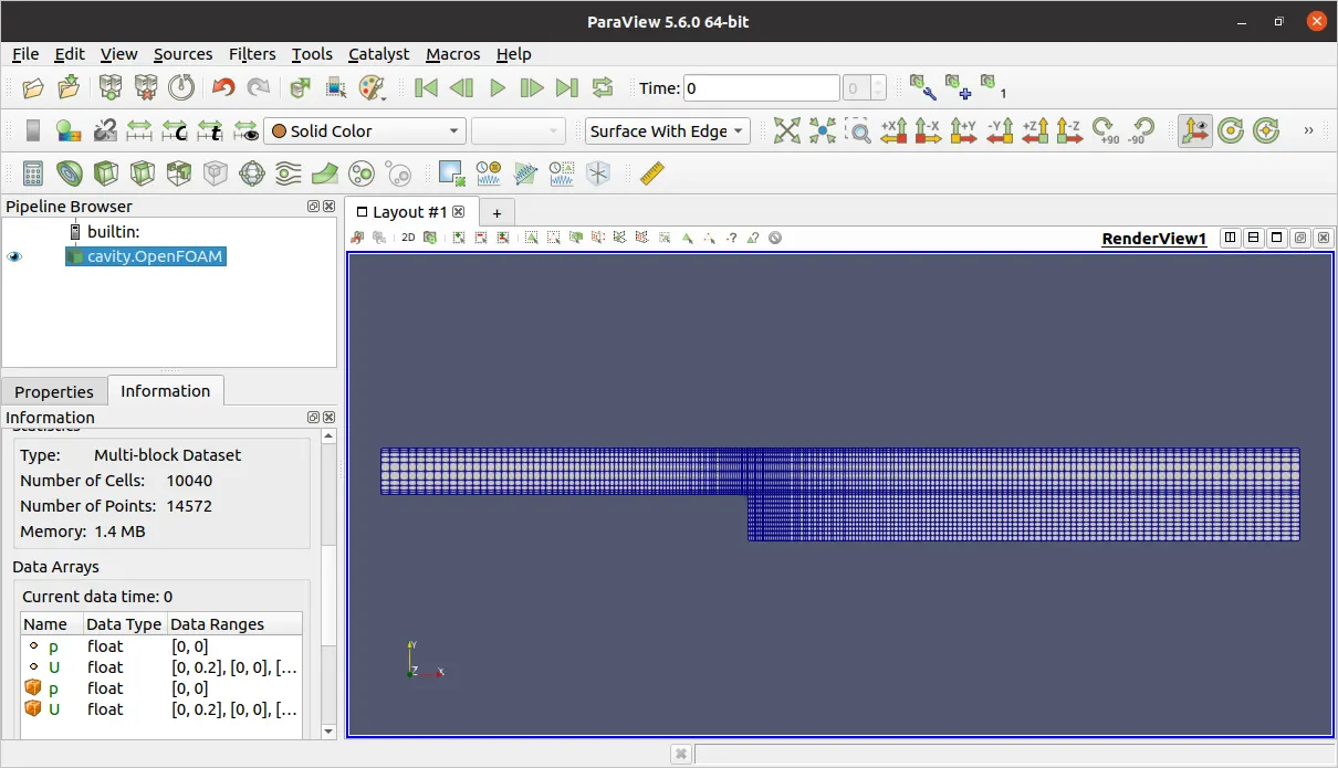
velocitu : U
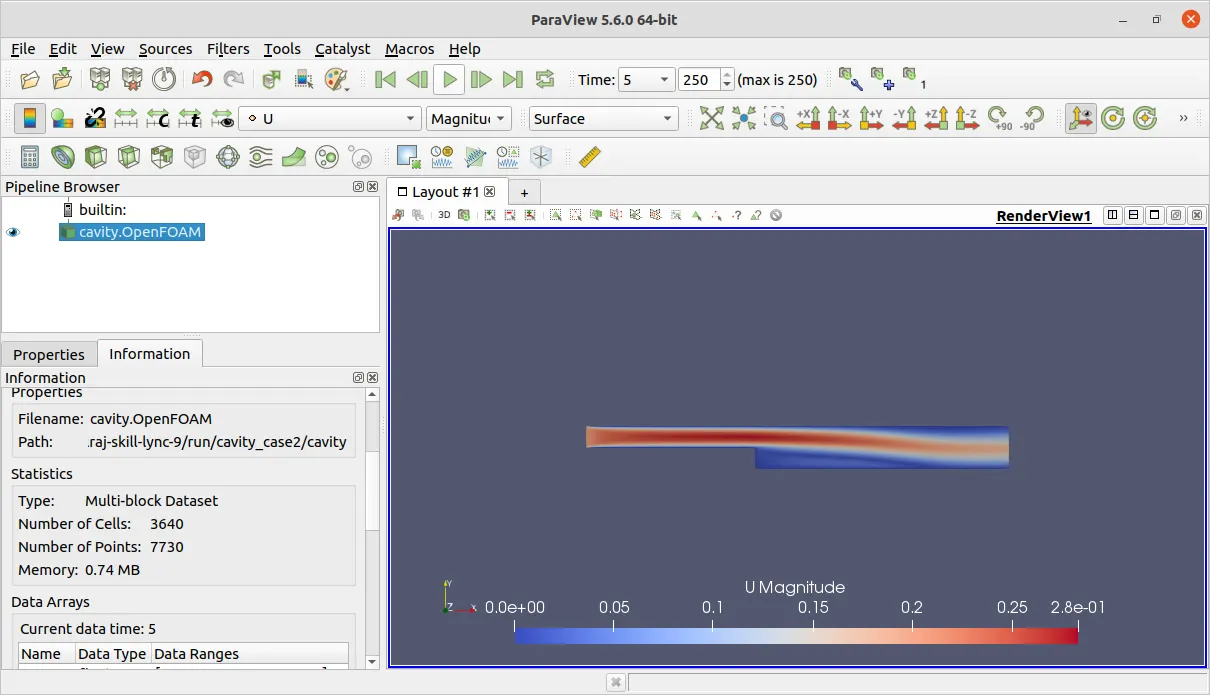
pressure p
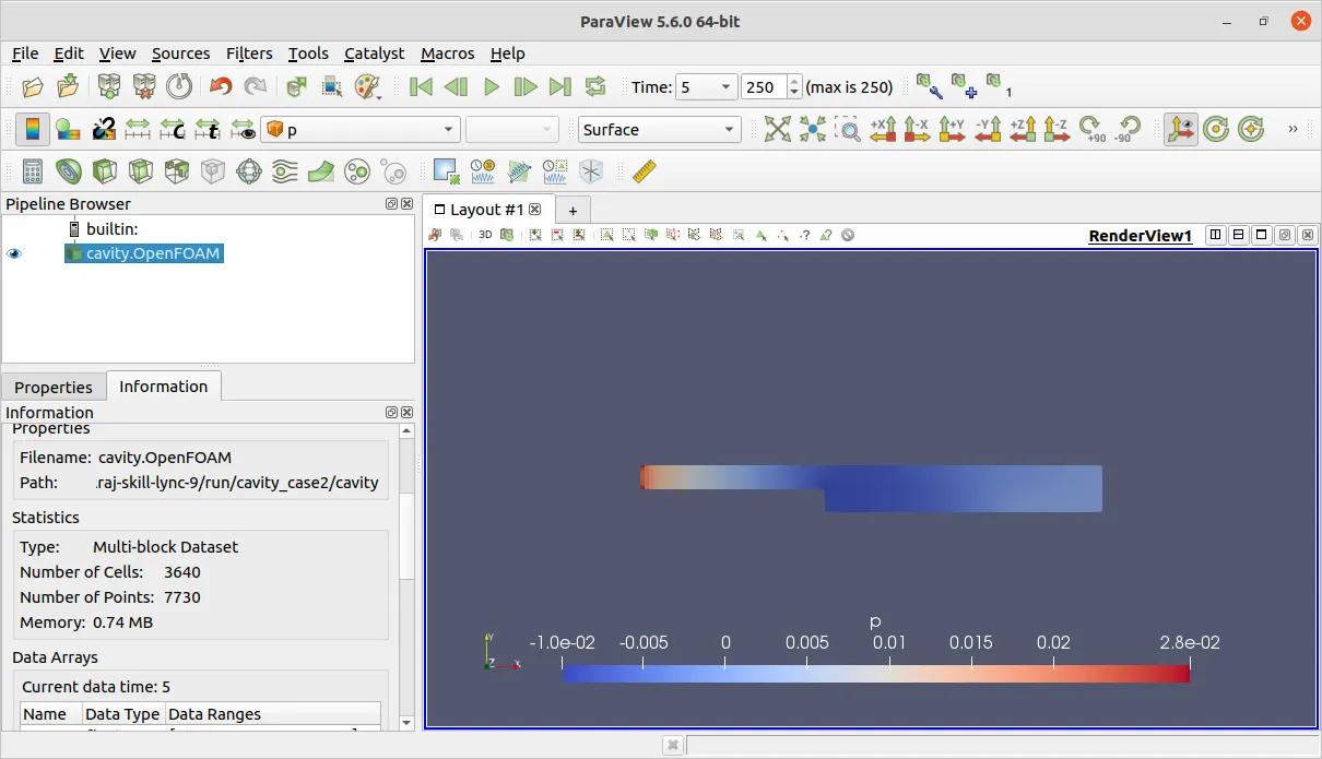
Velocity Profile Gif
Velocity Profile at x= 0.085
Conclusion :
Comparing velocity plots without grading and with a grading factor of 0.2 may suggest that grading disrupts accuracy. However, this is misleading. Examination reveals that while the mesh is fine along the X-axis at the step wall, it is coarse along the Y-axis. This discrepancy causes inaccuracies, particularly evident at the 0.085 point along the Y-axis. Visualizing this with coarse and fine meshes on the left and right sides respectively, underscores the issue. The finer mesh yields a smoother plot overall, with only a minor spike near 0.01, whereas the coarse mesh exhibits jaggedness, especially evident at the curve's apex. This highlights how mesh refinement, particularly in areas of significant flow variation, impacts result accuracy.