Week 8 - Simulation of a backward facing step in OpenFOAM
Simulation of a backward facing step in OpenFOAM
AIM: To simulate incompressible laminar viscous flow through the backward facing step geometry.
Introduction:
In this task, the flow through the backward-facing step has been modelled using the OPENFOAM software's icoFOAM solver. As a consequence, it is possible to produce a velocity and pressure profile for various mesh grading factors. Below are the specifications for a specific backward-facing step. Additionally, simulate the flow using various garding factors.
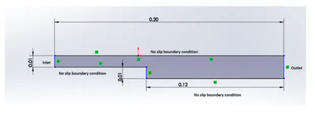
Nature of flow: Incompressible flow
Block Mesh specification:
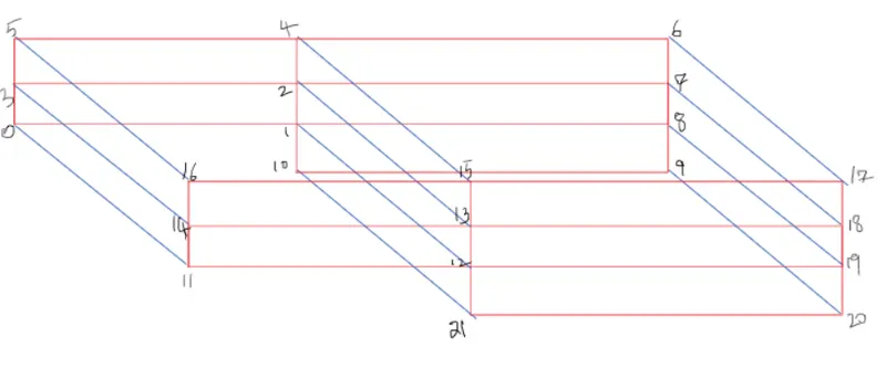
Number of blocks = 5
Arrangement of blocks is as follow:

To understand it more clearly take a look at figure below:
Mesh Specification:
- Numbetr of cells along the X-direction(longer dimension) = 200
- Number of cells along the y-direction = 10
Desired Output:
Run the first simulation without grading factor
Run thesecond simulation with mesh grading factor of 0.2, 0.5, 0.8. Compare the effect of grading factor with necessary contour & plots.
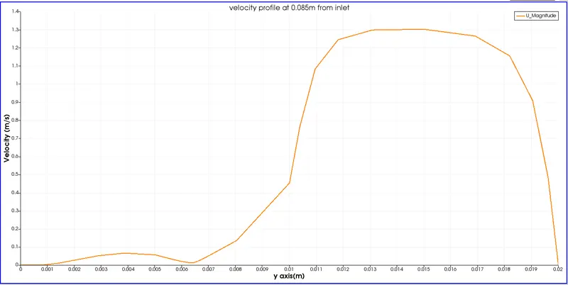
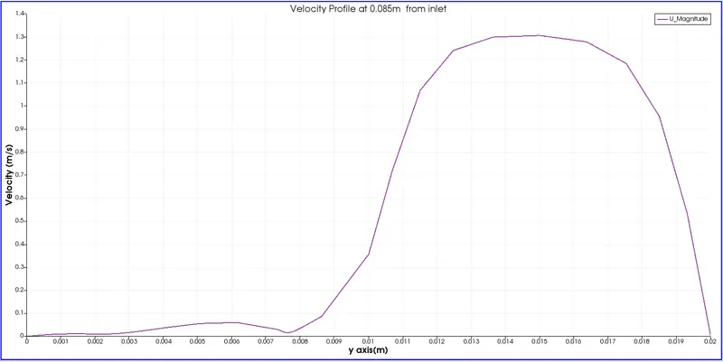
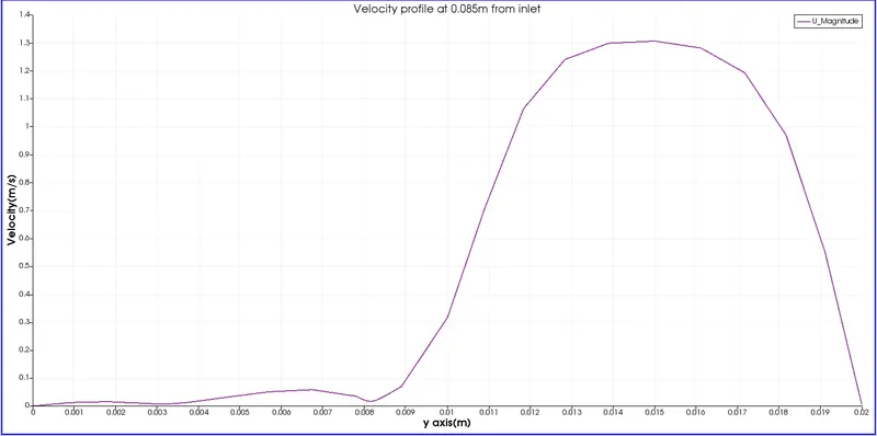
Measure the velocity profile at 0.085m from the inlet of the geometry with a line plot.
Compare velocity magnitude contour near the step region for the above menstioned garding factors.
OpenFoam Code for creating given geometry using BlockMesh
/*--------------------------------*- C++ -*----------------------------------*
  =========                 |
  \      /  F ield         | OpenFOAM: The Open Source CFD Toolbox
   \    /   O peration     | Website:  https://openfoam.org
    \  /    A nd           | Version:  8
     \/     M anipulation  |
*---------------------------------------------------------------------------*/
FoamFile
{
    version     2.0;
    format      ascii;
    class       dictionary;
    object      blockMeshDict;
}
// * * * * * * * * * * * * * * * * * * * * * * * * * * * * * * * * * * * * * //

convertToMeters 1;

vertices
(
    (0 0 0) //0
    (0.08 0 0) //1
    (0.08 0.005 0) //2
    (0 0.005 0)  //3
    (0.08 0.01 0)  //4
    (0 0.01 0)  //5
    (0.2 0.01 0)  //6
    (0.2 0.005 0)  //7
    (0.2 0 0) //8
    (0.2 -0.01 0) //9
    (0.08 -0.01 0) //10

    (0 0 0.001)  //11
    (0.08 0 0.001)  //12
    (0.08 0.005 0.001)  //13
    (0 0.005 0.001)  //14
    (0.08 0.01 0.001)  //15
    (0 0.01 0.001)  //16
    (0.2 0.01 0.001)  //17
    (0.2 0.005 0.001)  //18
    (0.2 0 0.001)  //19
    (0.2 -0.01 0.001)  //20
    (0.08 -0.01 0.001) // 21
);
blocks
(
    hex (0 1 2 3 11 12 13 14) (80 5 1) simpleGrading (0.2 5 1)
    hex (3 2 4 5 14 13 15 16) (80 5 1) simpleGrading (0.2 0.2 1)
    hex (2 7 6 4 13 18 17 15) (120 5 1) simpleGrading (5 0.2 1)
    hex (1 8 7 2 12 19 18 13) (120 5 1) simpleGrading (5 5 1)
    hex (10 9 8 1 21 20 19 12) (120 10 1) simpleGrading (5 5 1)
);

edges
(
);

boundary
(
    inlet
    {
        type patch;
        faces
        (
            (0 11 14 3)
            (3 14 16 5)
        );
    }
    outlet
    {
    	type patch;
    	faces
    	(
    		(9 8 19 20)
    		(8 7 18 19)
    		(7 6 17 18)
    	);

    }
    upperwalls
    {
    	type wall;
    	faces
    	(

    		(5 16 15 4)
    		(4 15 17 6)

    	);

    }
    lowerwalls
    {
    	type wall;
    	faces
    	(
    		(0 1 12 11)
    		(10 9 20 21)
    		(10 21 12 1)

    	);

    }
    frontAndBack
    {
        type empty;
        faces
        (
            (3 2 1 0)
            (5 4 2 3)
            (4 6 7 2)
            (2 7 8 1)
            (1 8 9 10)
            (11 12 13 14)
            (14 13 15 16)
            (13 18 17 15)
            (12 19 18 13)
            (21 20 19 12)

        );
    }
 );
mergePatchPairs
(
);


// ************************************************************************* //
In the above code code, inlet,outlet,upperwall,lowerwall,FrontAndback are user definied faces for creating boundary conditions.
Time-step Definition:
Run time t= 50 s
Time-step size dt = 0.0005 s
/*--------------------------------*- C++ -*----------------------------------*
  =========                 |
  \      /  F ield         | OpenFOAM: The Open Source CFD Toolbox
   \    /   O peration     | Website:  https://openfoam.org
    \  /    A nd           | Version:  8
     \/     M anipulation  |
*---------------------------------------------------------------------------*/
FoamFile
{
    version     2.0;
    format      ascii;
    class       dictionary;
    location    "system";
    object      controlDict;
}
// * * * * * * * * * * * * * * * * * * * * * * * * * * * * * * * * * * * * * //

application     icoFoam;

startFrom       startTime;

startTime       0;

stopAt          endTime;

endTime         0.5;

deltaT          0.0005;

writeControl    timeStep;

writeInterval   20;

purgeWrite      0;

writeFormat     ascii;

writePrecision  6;

writeCompression off;

timeFormat      general;

timePrecision   6;

runTimeModifiable true;


// ************************************************************************* //
Boundary Conditions
Velocity for user defined faces.
/*--------------------------------*- C++ -*----------------------------------*
  =========                 |
  \      /  F ield         | OpenFOAM: The Open Source CFD Toolbox
   \    /   O peration     | Website:  https://openfoam.org
    \  /    A nd           | Version:  8
     \/     M anipulation  |
*---------------------------------------------------------------------------*/
FoamFile
{
    version     2.0;
    format      ascii;
    class       volVectorField;
    object      U;
}
// * * * * * * * * * * * * * * * * * * * * * * * * * * * * * * * * * * * * * //

dimensions      [0 1 -1 0 0 0 0];

internalField   uniform (0 0 0);

boundaryField
{
    inlet
    {
        type            fixedValue;
        value           uniform (1 0 0);
    }

    outlet
    {
        type            zeroGradient;
    }
    upperwalls
    {
    	type		noSlip;
    }

    lowerwalls
    {
    	type		noSlip;
    }

    frontAndBack
    {
        type            empty;
    }

}

// ************************************************************************* //
Pressure for user defined faces.
--------------------------------*- C++ -*----------------------------------*
  =========                 |
  \      /  F ield         | OpenFOAM: The Open Source CFD Toolbox
   \    /   O peration     | Website:  https://openfoam.org
    \  /    A nd           | Version:  8
     \/     M anipulation  |
*---------------------------------------------------------------------------*/
FoamFile
{
    version     2.0;
    format      ascii;
    class       volScalarField;
    object      p;
}
// * * * * * * * * * * * * * * * * * * * * * * * * * * * * * * * * * * * * * //

dimensions      [0 2 -2 0 0 0 0];

internalField   uniform 0;

boundaryField
{
    inlet
    {
        type            zeroGradient;
    }

    outlet
    {
        type            fixedValue;
        value		 uniform 0;
    }
    upperwalls
    {
    	type		 zeroGradient;

    }

    lowerwalls
    {
    	type		 zeroGradient;

    }

    frontAndBack
    {
        type            empty;
    }
 }

// ************************************************************************* //
Kinematic viscosity of working fluid(Air) = 1.48e-5 m2s
/*--------------------------------*- C++ -*----------------------------------*
  =========                 |
  \      /  F ield         | OpenFOAM: The Open Source CFD Toolbox
   \    /   O peration     | Website:  https://openfoam.org
    \  /    A nd           | Version:  8
     \/     M anipulation  |
*---------------------------------------------------------------------------*/
FoamFile
{
    version     2.0;
    format      ascii;
    class       dictionary;
    location    "constant";
    object      transportProperties;
}
// * * * * * * * * * * * * * * * * * * * * * * * * * * * * * * * * * * * * * //

nu              [0 2 -1 0 0 0 0] 1.48e-5;


// ************************************************************************* //
Mesh Grading Factor(MGF)
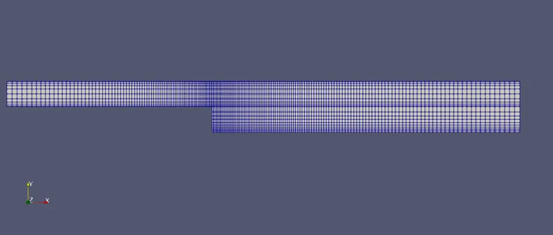
It is used to strech the mesh in particular axis. For our challenge, we are using 0.2, 0.5 and 0.8 as our grading factors.
OpenFoam Code for creating the mesh with MGF =0.2
blocks
(
    hex (0 1 2 3 11 12 13 14) (80 5 1) simpleGrading (0.2 5 1)
    hex (3 2 4 5 14 13 15 16) (80 5 1) simpleGrading (0.2 0.2 1)
    hex (2 7 6 4 13 18 17 15) (120 5 1) simpleGrading (5 0.2 1)
    hex (1 8 7 2 12 19 18 13) (120 5 1) simpleGrading (5 5 1)
    hex (10 9 8 1 21 20 19 12) (120 10 1) simpleGrading (5 5 1)
);
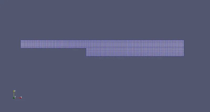
The geometry after meshing,
OpenFoam code for creating mesh with MGF = 0.5
blocks
(
    hex (0 1 2 3 11 12 13 14) (80 5 1) simpleGrading (0.5 2 1)
    hex (3 2 4 5 14 13 15 16) (80 5 1) simpleGrading (0.5 0.5 1)
    hex (2 7 6 4 13 18 17 15) (120 5 1) simpleGrading (2 0.5 1)
    hex (1 8 7 2 12 19 18 13) (120 5 1) simpleGrading (2 2 1)
    hex (10 9 8 1 21 20 19 12) (120 10 1) simpleGrading (2 2 1)
);
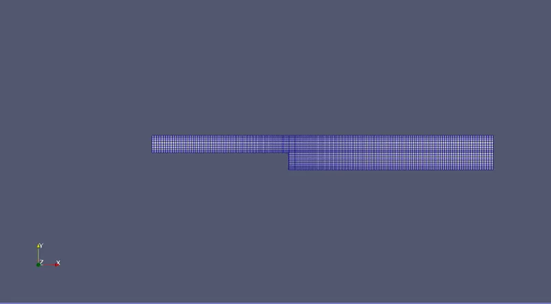
The geometry after meshing
OpenFoam code for creating mesh with MGF= 0.8
blocks
(
    hex (0 1 2 3 11 12 13 14) (80 5 1) simpleGrading (0.8 1.25 1)
    hex (3 2 4 5 14 13 15 16) (80 5 1) simpleGrading (0.8 0.8 1)
    hex (2 7 6 4 13 18 17 15) (120 5 1) simpleGrading (1.25 0.8 1)
    hex (1 8 7 2 12 19 18 13) (120 5 1) simpleGrading (1.25 1.25 1)
    hex (10 9 8 1 21 20 19 12) (120 10 1) simpleGrading (1.25 1.25 1)
);
Geometry after meshing
Results
- Velocity profile for MGF =0.2
- Velocity profile for MGF =0.5
- Velocity profile for MGF =0.8
- Animation of flow through backward facing step
5. Animation of flow through backward facing step(MGF = 0.5)
6.Animation of flow through backward facing step(MGF = 0.8)
Conclusion: