Week 8 - Simulation of a backward facing step in OpenFOAM
SIMULATION OF A BACKWARD FACING STEP IN OPENFOAM:
Backward facing step is a internal flow problem in fluid dynamics and its a geometry for visualizing recirculating flow and validating turbulence model.i.e.,to predict recirculating flow.
The purpose of the study was to investigate the flow behavior through the backward facing step and to calculate flow separation and recirculation zone.
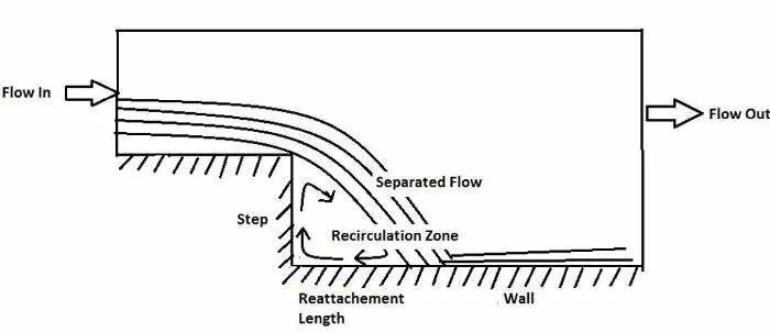
Simulate an incompressible-laminar-viscous flow through the backward facing step geometry by transient simulation.
Based on the described physics of the flow,the solver can be chosen.
After that,perform 2 case studies as described below and compare the results.
Case 1 - Simulate the flow without using any grading factor (i.e., GF = 1)
Case 2 - Simulate the flow with grading factor of 0.2. The cells should be finer near the walls (includig the step wall).
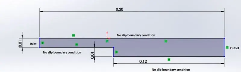
STEPS:
- Choose a right solver for the simulation
- Followed by solver tutorial to create geometry and mesh.
- Assign boundary condition and initial conditions.
- Post-process the results and plot it.
ASSUMPTIONS TO CHOOSE A SOLVER:
- Newtonian fluid and the flow is incompressible and laminar
- When there is Low reynolds number,fluid is laminar.
- Icofoam is the transient solver for incompressible, laminar flow of Newtonian fluids
- The solver tutorial from incompressible icofoam called cavity is chosen
Let us consider creating the geometry using 5 blocks as shown in the figure below,

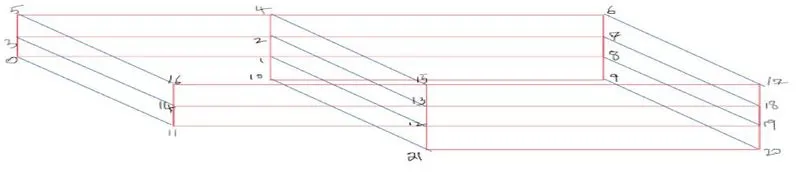
Start indexing the Vertices on the back side of the blocks and front side of the blocks and number it as our comfort.
Then, to define the blocks,specify the right order of vertex indices.
Defining the vertices of the all 5 blocks(back side and front side) in the Geometry.
To specify the initial and boundary conditions.
If we are looking at these faces from the outside, the define the inlet boundary in clockwise direction wheres in outside, define it in anticlockwise direction.
Front and backside are empty and no slipwall at top(block 2,3),bottom(block1,5),stepside.
BLOCKMESH :
The mesh is generated from a dictionary file named blockMeshDict located in the constant/polyMesh directory of a case. blockMesh reads this dictionary, generates the mesh and writes out the mesh data to point and faces, cellsand boundary files in the same directory.
Number of mesh points along x,y,z are n_x,n_y,n_z
The simple grading description specifies uniform expansions in the local `x_1,x_2,x_3` directions respectively with only 3 expansion ratios.Its also known as mesh stretching.
/*--------------------------------*- C++ -*----------------------------------*\
  =========                 |
  \\      /  F ield         | OpenFOAM: The Open Source CFD Toolbox
   \\    /   O peration     | Website:  https://openfoam.org
    \\  /    A nd           | Version:  8
     \\/     M anipulation  |
\*---------------------------------------------------------------------------*/
FoamFile
{
    version     2.0;
    format      ascii;
    class       dictionary;
    object      blockMeshDict;
}
// * * * * * * * * * * * * * * * * * * * * * * * * * * * * * * * * * * * * * //

convertToMeters 0.1;

vertices
(
    (0 0 0)   //vertice 0
    (8 0 0)   //vertice 1
    (8 0.5 0)  //vertice 2
    (0 0.5 0) //vertice 3
    (8 1 0)   //vertice 4
    (0 1 0)   //vertice 5
    (20 1 0)  //vertice 6
    (20 0.5 0)//vertice 7
    (20 0 0)  //vertice 8
    (20 -1 0) //vertice 9
    (8 -1 0)  //vertice 10
    (0 0 0.01)//vertice 11
    (8 0 0.01)//vertice 12
    (8 0.5 0.01)//vertice 13
    (0 0.5 0.01)//vertice 14
    (8 1 0.01) //vertice15
    (0 1 0.01) //vertice 16
    (20 1 0.01)//vertice 17
    (20 0.5 0.01)//vertice 18
    (20 0 0.01) //vertice 19
    (20 -1 0.01)//vertice 20
    (8 -1 0.01) //vertice 21


);

blocks
(
    hex (0 1 2 3 11 12 13 14) (100 20 1) simpleGrading (1 1 1)
    hex (3 2 4 5 14 13 15 16) (100 20 1) simpleGrading (1 1 1)
    hex (2 7 6 4 13 18 17 15) (100 20 1) simpleGrading (1 1 1)
    hex (1 8 7 2 12 19 18 13) (100 20 1) simpleGrading (1 1 1)
    hex (10 9 8 1 21 20 19 12) (100 20 1) simpleGrading (1 1 1)

);

edges
(
);

boundary
(
    inlet
    {
        type wall;
        faces
        (
            (0 11 14 3)
            (3 14 16 5)
        );
    }
    outlet
    {
        type wall;
        faces
        (
            (7 6 17 18)
            (8 7 18 19)
            (9 8 19 20)
        );
    }
    frontAndBack
    {
        type empty;
        faces
        (
            (0 1 2 3)
            (3 2 4 5)
            (10 9 8 1)
            (1 8 7 2)
            (2 7 6 4)
            (11 12 13 14)
            (14 13 15 16)
            (21 20 19 12)
            (12 19 18 13)
            (13 18 17 15)
        );
    }
    noSlipwall
    {
        type wall;
        faces
        (
            (16 15 4 5)
            (15 17 6 4)
            (10 21 12 1)
            (0 1 12 11)
            (10 9 20 21)

        );
    }
);

mergePatchPairs
(
);

// ************************************************************************* //
TRANSPORT PROPERTIES:
Transport properties of fluid are set in fluid regions.
Newtonian fluid is assumed and dynamic viscosity is set to 1.5e^-6 which corresponds to the air at 20degcel.
Due to incompressible behaviour,fluid doesn't change its density throughout the flow.So we can use kinematic pressure.
Kinematic pressure is where p is the pressure and density is constant.
`p_k=p_s/ρ[m^2/s^2]`
/*--------------------------------*- C++ -*----------------------------------*\
  =========                 |
  \\      /  F ield         | OpenFOAM: The Open Source CFD Toolbox
   \\    /   O peration     | Website:  https://openfoam.org
    \\  /    A nd           | Version:  8
     \\/     M anipulation  |
\*---------------------------------------------------------------------------*/
FoamFile
{
    version     2.0;
    format      ascii;
    class       dictionary;
    location    "constant";
    object      transportProperties;
}
// * * * * * * * * * * * * * * * * * * * * * * * * * * * * * * * * * * * * * //

nu              [0 2 -1 0 0 0 0] 1.5e-6;


// ************************************************************************* //
CONTROL DICTIONARY:
The controldict dictionary is used to specify the main case controls. This includes, e.g. timing information, write format, and optional libraries that can be loaded at run time.
Start time is 0 end time is 20.But in code,after 20 timestep to 30 timestep has made to run
/*--------------------------------*- C++ -*----------------------------------*\
  =========                 |
  \\      /  F ield         | OpenFOAM: The Open Source CFD Toolbox
   \\    /   O peration     | Website:  https://openfoam.org
    \\  /    A nd           | Version:  8
     \\/     M anipulation  |
\*---------------------------------------------------------------------------*/
FoamFile
{
    version     2.0;
    format      ascii;
    class       dictionary;
    location    "system";
    object      controlDict;
}
// * * * * * * * * * * * * * * * * * * * * * * * * * * * * * * * * * * * * * //

application     icoFoam;

startFrom       startTime;

startTime       20;

stopAt          endTime;

endTime         30;

deltaT          0.005;

writeControl    timeStep;

writeInterval   20;

purgeWrite      0;

writeFormat     ascii;

writePrecision  6;

writeCompression off;

timeFormat      general;

timePrecision   6;

runTimeModifiable true;


// ************************************************************************* //
BOUNDARY CONDITIONS:
VELOCITY :
Inlet velocity will be fixed value 0.1m/s^2.
If we choose higher velocity,then it will surpass the domain very quickly.Turbulence realization won't happen.
Dimensions are [0 1 -1 0 0 0 0] i.e.,expressed as [ kg m s k mol A cd]
Internal field defines values in cell volumes of the mesh.These are used as inlet condition at the beginning of a simulation.They are kept to be constant value on uniform value to the each cell and if non-uniform different values to each cell.
Internal field unifrom(0 0 0).velocity is unifrom over three dimensions and v=0 at initial condition
Front and back are empty as we are not in 3D simuationof backward facing step.
/*--------------------------------*- C++ -*----------------------------------*\
  =========                 |
  \\      /  F ield         | OpenFOAM: The Open Source CFD Toolbox
   \\    /   O peration     | Website:  https://openfoam.org
    \\  /    A nd           | Version:  8
     \\/     M anipulation  |
\*---------------------------------------------------------------------------*/
FoamFile
{
    version     2.0;
    format      ascii;
    class       volVectorField;
    location    "0";
    object      U;
}
// * * * * * * * * * * * * * * * * * * * * * * * * * * * * * * * * * * * * * //

dimensions      [0 1 -1 0 0 0 0];

internalField   uniform (0 0 0);

boundaryField
{
    inlet
    {
        type            fixedValue;
        value           uniform (0.1 0 0);
    }
    outlet
    {
        type            zeroGradient;
    }
    noSlipwall
    {
        type            noSlip;
    }

   frontAndBack
    {
        type            empty;
    }

}


// ************************************************************************* //
PRESSURE:
Pressure is uniform,0 represents gauge pressure.
Inlet pressure is zero gradient(Neuman BC)
Outlet pressure will be uniform 0 at 1atm(Dirichlet BC)
At no slipwall boundary,pressure is said to be zero gradient(Neumann BC)
Zero gradient boundary condition simply extrapolates the quantity to the patch from the nearest cell value. The meaning is, the quantity is developed in space and its gradient is equal to zero in direction perpendicular to the patch (perpendicular to the boundary).Such that outlet pressure is to be calculated,inlet is zero gradient.
/*--------------------------------*- C++ -*----------------------------------*\
  =========                 |
  \\      /  F ield         | OpenFOAM: The Open Source CFD Toolbox
   \\    /   O peration     | Website:  https://openfoam.org
    \\  /    A nd           | Version:  8
     \\/     M anipulation  |
\*---------------------------------------------------------------------------*/
FoamFile
{
    version     2.0;
    format      ascii;
    class       volScalarField;
    location    "0";
    object      p;
}
// * * * * * * * * * * * * * * * * * * * * * * * * * * * * * * * * * * * * * //

dimensions      [0 2 -2 0 0 0 0];

internalField   uniform 0;

boundaryField
{
    outlet
    {
        type            fixedValue;
        value           uniform 0;
    }
    inlet
    {
        type            zeroGradient;
    }
    noSlipwall
    {
        type            zeroGradient;
    }

   frontAndBack
    {
        type            empty;
    }

}


// ************************************************************************* //
BLOCKMESH WITH GRADING FACTOR 0.2:
Simulate the flow with grading factor of 0.2. The cells should be finer near the walls (includig the step wall).
Grading factor is the full cell expansion description gives a ratio for each edge of the block
If size of the end cell is larger than size of first cell, Grading factor is to be >1.
If size of the end cell is smaller than size of first cell, Grading factor is to be <1.
/*--------------------------------*- C++ -*----------------------------------*\
  =========                 |
  \\      /  F ield         | OpenFOAM: The Open Source CFD Toolbox
   \\    /   O peration     | Website:  https://openfoam.org
    \\  /    A nd           | Version:  8
     \\/     M anipulation  |
\*---------------------------------------------------------------------------*/
FoamFile
{
    version     2.0;
    format      ascii;
    class       dictionary;
    object      blockMeshDict;
}
// * * * * * * * * * * * * * * * * * * * * * * * * * * * * * * * * * * * * * //

convertToMeters 0.1;

vertices
(
    (0 0 0)   //vertice 0
    (8 0 0)   //vertice 1
    (8 0.5 0)  //vertice 2
    (0 0.5 0) //vertice 3
    (8 1 0)   //vertice 4
    (0 1 0)   //vertice 5
    (20 1 0)  //vertice 6
    (20 0.5 0)//vertice 7
    (20 0 0)  //vertice 8
    (20 -1 0) //vertice 9
    (8 -1 0)  //vertice 10
    (0 0 0.01)//vertice 11
    (8 0 0.01)//vertice 12
    (8 0.5 0.01)//vertice 13
    (0 0.5 0.01)//vertice 14
    (8 1 0.01) //vertice15
    (0 1 0.01) //vertice 16
    (20 1 0.01)//vertice 17
    (20 0.5 0.01)//vertice 18
    (20 0 0.01) //vertice 19
    (20 -1 0.01)//vertice 20
    (8 -1 0.01) //vertice 21


);

blocks
(
    hex (0 1 2 3 11 12 13 14) (100 20 1) simpleGrading (0.2 5 1)
    hex (3 2 4 5 14 13 15 16) (100 20 1) simpleGrading (0.2 0.2 1)
    hex (2 7 6 4 13 18 17 15) (100 20 1) simpleGrading (5 0.2 1)
    hex (1 8 7 2 12 19 18 13) (100 20 1) simpleGrading (5 5 1)
    hex (10 9 8 1 21 20 19 12) (100 20 1) simpleGrading (5 5 1)

);

edges
(
);

boundary
(
    inlet
    {
        type wall;
        faces
        (
            (0 11 14 3)
            (3 14 16 5)
        );
    }
    outlet
    {
        type wall;
        faces
        (
            (7 6 17 18)
            (8 7 18 19)
            (9 8 19 20)
        );
    }
    frontAndBack
    {
        type empty;
        faces
        (
            (0 1 2 3)
            (3 2 4 5)
            (10 9 8 1)
            (1 8 7 2)
            (2 7 6 4)
            (11 12 13 14)
            (14 13 15 16)
            (21 20 19 12)
            (12 19 18 13)
            (13 18 17 15)
        );
    }
    noSlipwall
    {
        type wall;
        faces
        (
            (16 15 4 5)
            (15 17 6 4)
            (10 21 12 1)
            (0 1 12 11)
            (10 9 20 21)

        );
    }
);

mergePatchPairs
(
);

// ************************************************************************* //
After checkmesh,post process the results in paraview software.
GRADING FACTOR 1:
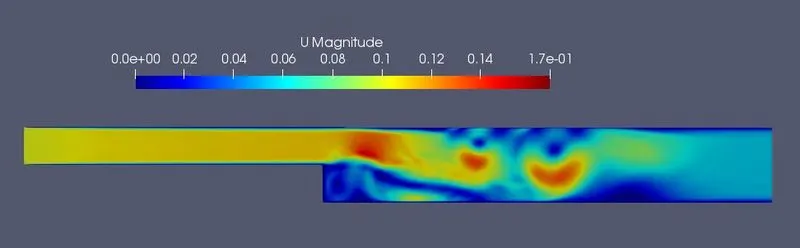
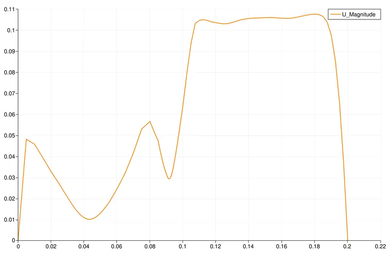
Here the flow gets detached from the wall and is seperated.At seperation point,there is slight variation in flow and low pressure region is created which causes the flow to recirculate.The region created from the rise is known as recirculation zone or wake region
When the fluid flows through the pipe,a boundary layer is created against walls of the pipe and its builds perpendicular to it.velocity is low at the surface and goes on increasing as we move up from the wall.
GRADING FACTOR 1:
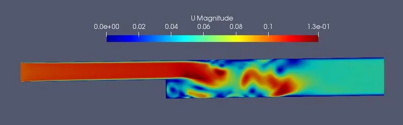
GRADING FACTOR 0.2:
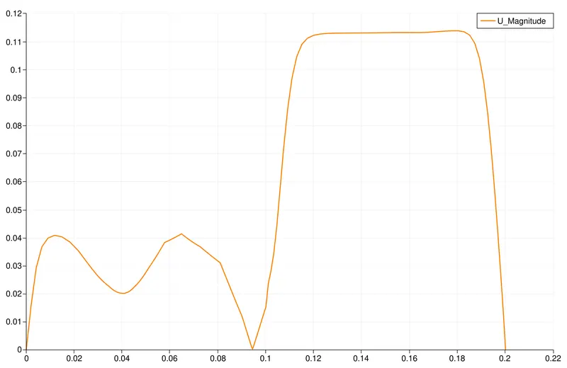
GRADING FACTOR 0.2:
RESULTS:
If the mesh is not fine,it gives average results because of capturing less elements at each node.
To capture accurate results,its required for finer mesh to capture flow properties of fluid.
By comparing both the plots,grading factor 0.2 gives better results than simple grading1
Velocity magnitude profiles gives similar results for both cases in general ,at 0.085m there is decrease in velocity but with a mesh grading factor,finer results are obtained with accurate results at step height and boundary walls.