Week 8 - Simulating Cyclone separator with Discrete Phase Modelling
Simulating Cyclone Separator with Discrete Phase Modelling
Aim: To perform analysis on the cyclone separator and calculate the separation efficiency and pressure drop.
Introduction: Cyclone separator
Cyclone separators are centrifugal separators that use inertial forces to separate particles. It has a tangential input and an axial discharge. It uses a high-velocity spinning column of air to separate particles with variable specific gravity. The control surfaces of the Cyclone Separator are as follows: Stream Input, Dust Outlet, and Filtered Air Outlet. The high-speed input stream creates a rotational flow that enters a helical channel within the cylindrical-conical body.
Particulate matter with a higher inertia than air collides with the chamber wall and is ejected from the air stream. This particulate matter is subsequently collected at the bottom, while the filtered air ascends to the top. The inside surfaces of the cyclone separator are smooth and bump-free, with incremental bends to maintain the laminar flow throughout the operation.
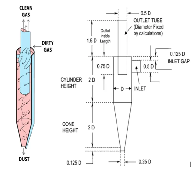
Empirical models used to calculate the cyclone separator efficiency are:
IOZIA AND LEITH MODEL:
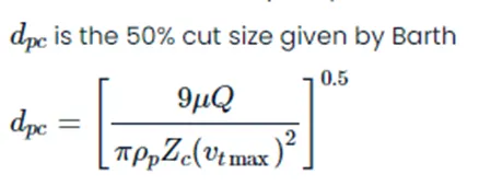
The logistic model created by Iozia and Leith (1990) is a modified version of the model developed by Barth (1956) and is based on force balance. The model states that a particle carried by a vortex is subject to two forces: centrifugal force, Z, and flow resistance, W. Core length, zc, and core diameter.
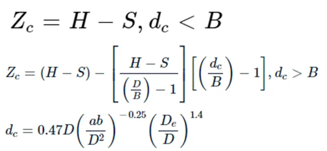
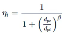
The core length zc and slope parameter expression are derived from statistical analysis of experimental data from a cyclone with D = 0.25 m. The collecting efficiency can be calculated using the particle diameter dpi.
LI AND WANG MODEL
Particle bounce or re-entrainment, as well as turbulent diffusion near the cyclone wall, are included in the Li and Wang (1989) model. The particle distribution in the cyclone is expressed analytically in two dimensions. The Li and Wang model was built on the following assumptions:
- For uncollected particles within the cyclones, the radial particle velocity and concentration profile are not constant.
- The following are the boundary conditions, considering the turbulent diffusion coefficient and particle bounce re-entrainment on the cyclone wall:
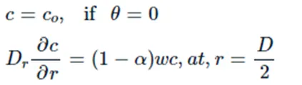
The tangential velocity is related to the radius of the cyclone by uRn =constant
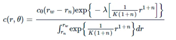
Where,
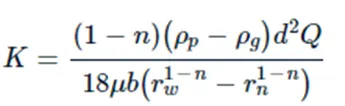 and
and 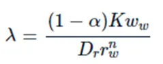
The resultant expression of the collection efficiency for the particle of any size is given as
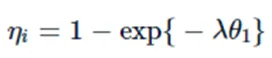 where,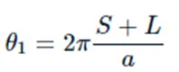
KOCH AND LICHT MODEL
The fundamentally turbulent nature of cyclones, as well as the distribution of gas residence periods within the cyclone, were noted by Koch and Licht collection theory. Koch and Licht describe particle mobility in the entry and collecting zones by using the following additional assumptions:
- The tangential velocity of a particle is equal to the tangential velocity of the gas flow, implying that there is no tangential slip between the particle and the gas.
- The tangential velocity is related to the radius of the cyclone by uRn = constant
A force balance and an equation on the particle collection yield the grade efficiency ηi.
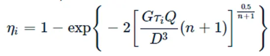
Where,
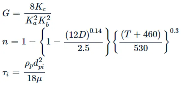
G is a factor related to the configuration of the cyclone, n is related to the vortex and τ is the relaxation term.
LAPPLE MODEL
The Lapple (1951) model was based on force balance and ignored flow resistance. According to Lapple, particles entering the cyclone are distributed uniformly over the input aperture. The particle that travels half the breadth of the cyclone to the wall is collected with 50% effectiveness. The semi-empirical relationship for estimating a 50% cut diameter, dpc, developed by Lapple is illustrated below.
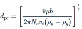
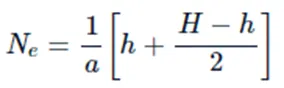
where Ne is the number of revolutions
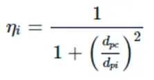
The efficiency of the collection of any size of particle is given by
Geometry Approach
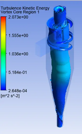
The reverse flow cyclones with tangential inlet are most often used for industrial gas cleaning. The inflowing fluid rotates within the chamber's main body, causing it to follow a spiral flow path. Any particles suspended in the fluid have increased radial acceleration. The larger particles migrate to the cone wall, spiraling downward to the chamber's base and escaping through the underflow. Because smaller particles travel at a slower rate, their distribution remains uniform throughout the flow. The vortex finder pulls those in the center upward, and they spiral up and out. The remainder is ejected, together with the coarse fraction, at the underflow.
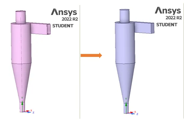
Open the workbench and save the project as a cyclone separator. Now open the fluent flow in the project and edit the geometry under the space claim option. Import the geometry to space claim. Extract the model for fluid volume by using the volume extraction tool under prepare tab. By using the suppress for physics option the original solid body will be hidden for further analysis. Save the file and exit the space claim.
Meshing
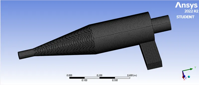
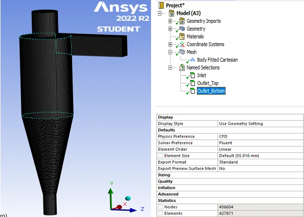
We can generate hexahedron components for the fluid volume since the geometry of the Cyclone Separator is simple. Other options, such as multizone and sweep, will, however, make the procedure highly time-consuming. As a result, for the development of structural mesh, we can use the "Cartesian" method accessible in Fluent's body fitting option because structural Mesh has the most powerful impact.
Setup:
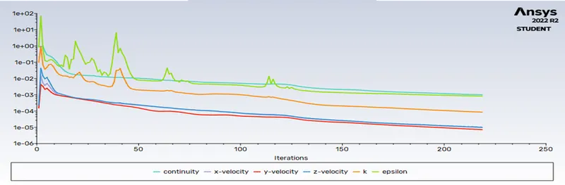
Gravity should be enabled in the y direction of -9.81m/s2 during the initial configuration of the pressure-based and steady-state solution. The viscous model is k-epsilon, RNG-swirl distributed flow with a typical standard wall function.

Discrete Phase Model [DPM]:
The discrete Phase Model is used in multiphase flows. To investigate particle behavior from both a Lagrangian and a discrete perspective, a discrete phase model (DPM) is used. The Lagrangian and Eulerian perspectives differ in that the Lagrangian perspective evaluates fluid behavior using particle tracking of a particulate flow, whereas the Eulerian perspective examines fluid behavior using the assumption of a finite volume element in the fluid flow path.
In DPM, there are two phases to consider: the continuous phase and the discrete phase. The fluid flowing within the fluid volume constitutes the first phase. ... the second phase is made up of the smaller particle, which is expected to interact with the former phase. In the current example, the discrete phase can also interchange momentum, mass, and energy with the fluid or continuous phase.
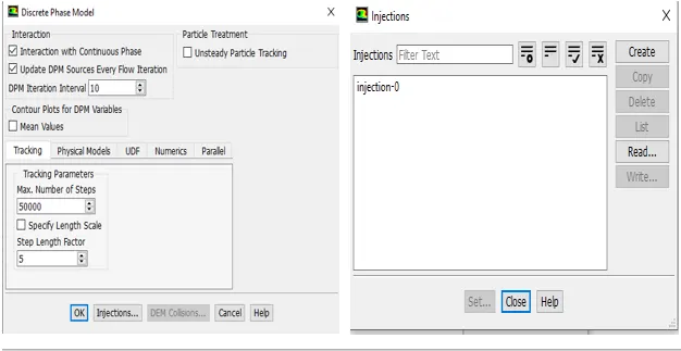
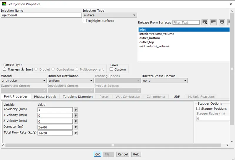
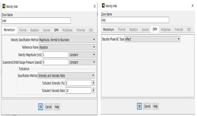
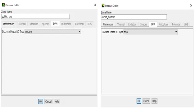
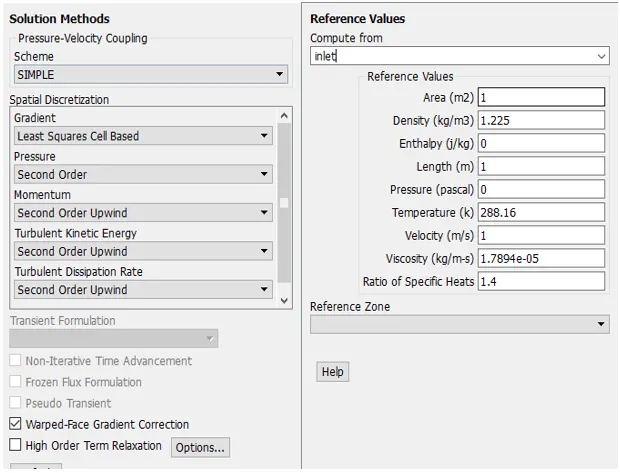
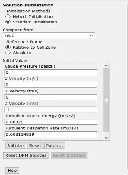
The simulations were run for two cases:
- To perform an analysis on a given cyclone separator model by varying the particle diameter from 1 μm to 5 μm and calculate the separation efficiency in each case. Discuss the results. [Use both the velocity's as 3m/sec.]
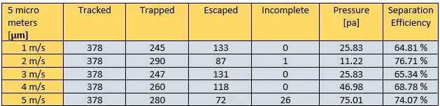
- To perform an analysis on a given cyclone separator model by varying the particle velocity from 1 m/sec to 5 m/sec and calculating the separation efficiency and pressure drop in each case. Discuss the results. [Use particle diameter size as 5 μm for all cases & keep flow velocity same as particle velocity]
Result
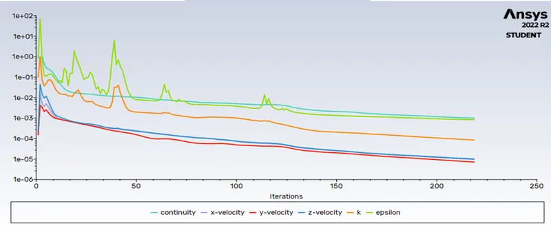
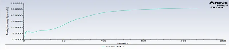
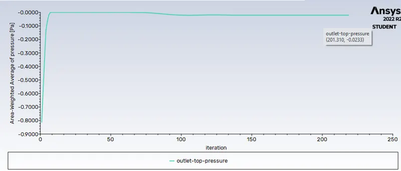
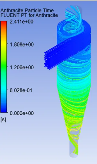
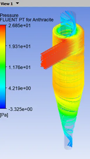
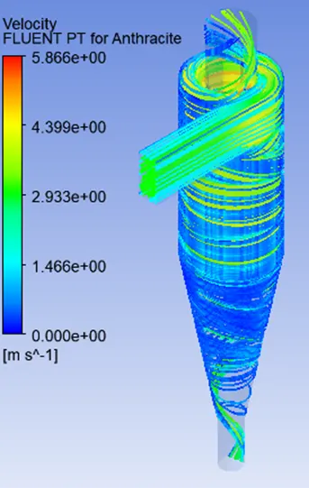
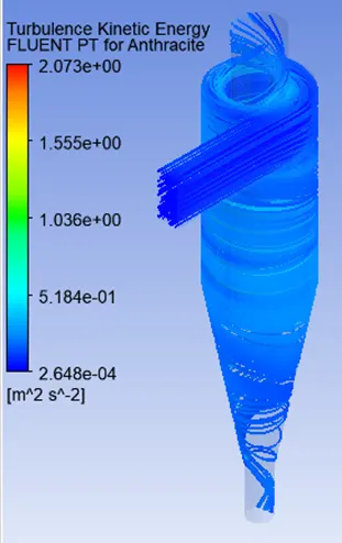
Case 1: 3 m/s, 1micrometer(mm)
 |
 |
 |
||
 |
||||

Separation Efficiency in % = (300 / 378) * 100
=79.36%
Separation Efficiency
Cyclone separators can typically remove between 50 and 99% of all particle matter in the flue gas. The ability of the cyclone separators to remove this material is mostly determined by particle size. When there is a lot of lighter particulate matter, fewer of these particles can be sorted out. As a result, cyclone separators perform best on exhaust gases containing a high concentration of large particle matter.
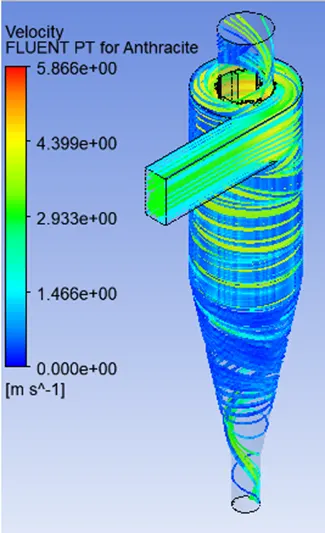
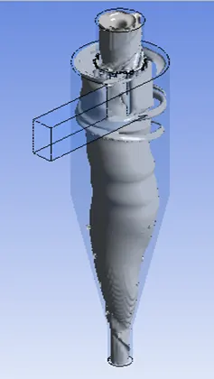
Case 1: 3 m/s, 2micrometer(mm)
 |
 |
 |
 |
||

Separation Efficiency in % = (303 / 378) * 100
= 80.15%
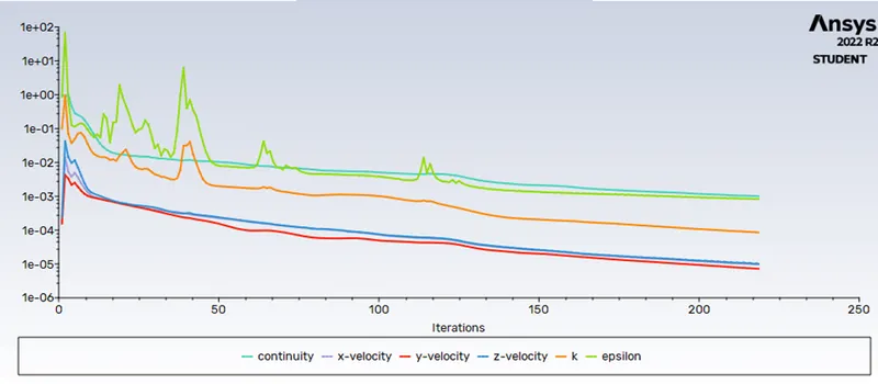
Case 1: 3 m/s, 3micrometer(µm)
 |
 |
 |
 |
||

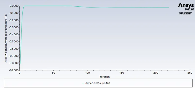
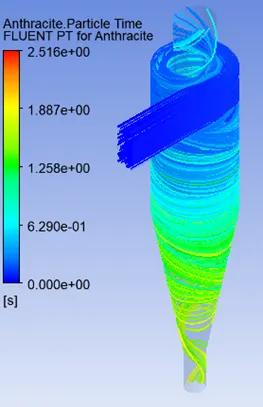
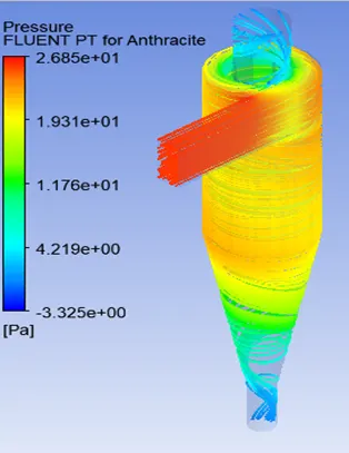
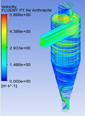
Separation Efficiency in % = (306 / 378) * 100
= 80.95%
Case 1: 3 m/s, 4micrometer(µm)
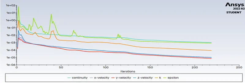
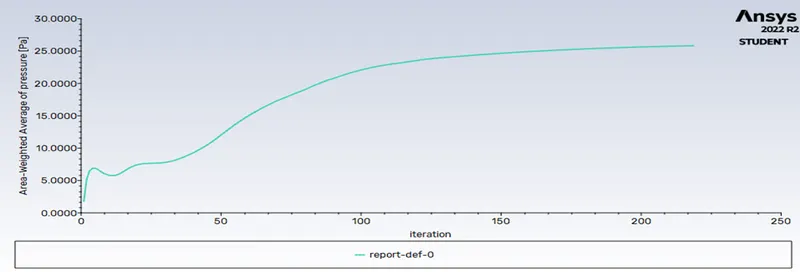
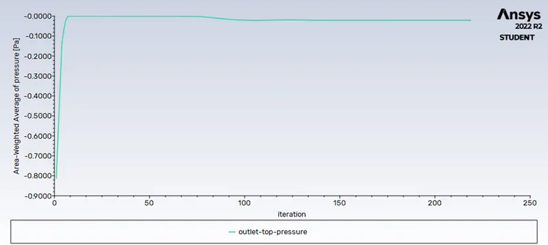
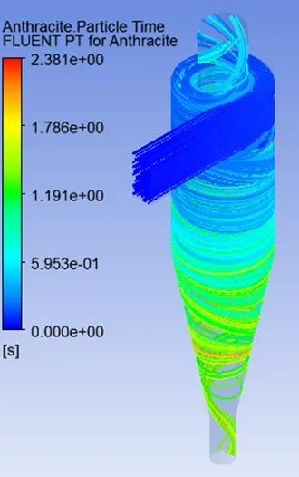 |
 |
 |
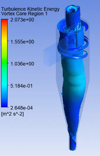 |

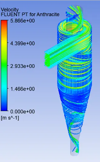
Separation Efficiency in % = (291 / 378) * 100
= 76.98%
Case 1: 3 m/s, 5micrometer(µm)
 |
 |
 |
 |

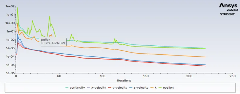
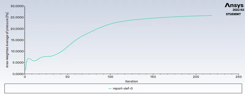
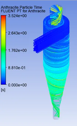
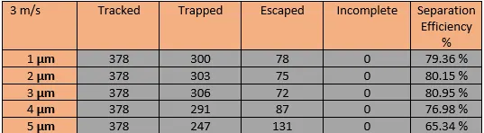
Separation Efficiency in % = (247 / 378) * 100
= 65.34%
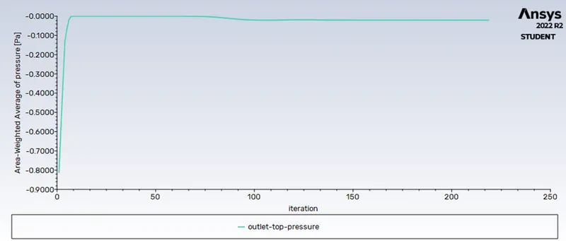
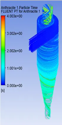
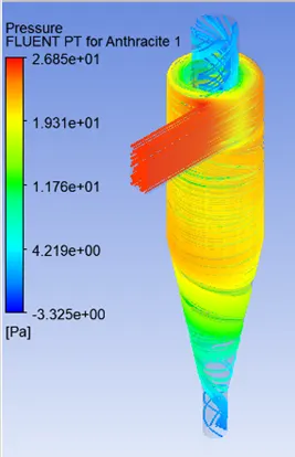
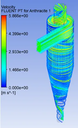
Case 2: 1 m/s, 5micrometer(µm)
 |
 |
 |
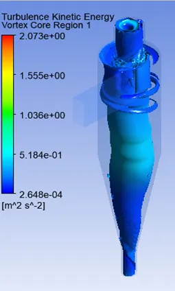 |

Separation Efficiency in % = (245 / 378) * 100
= 64.81 %
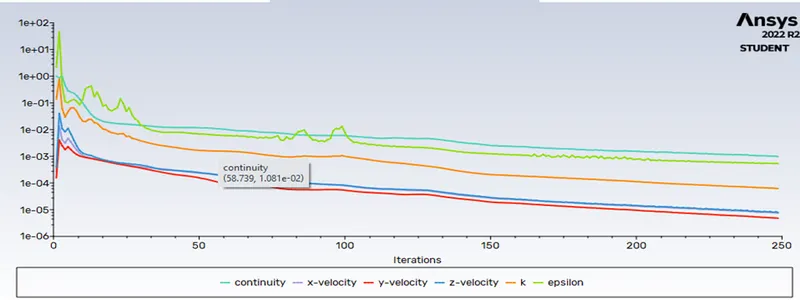
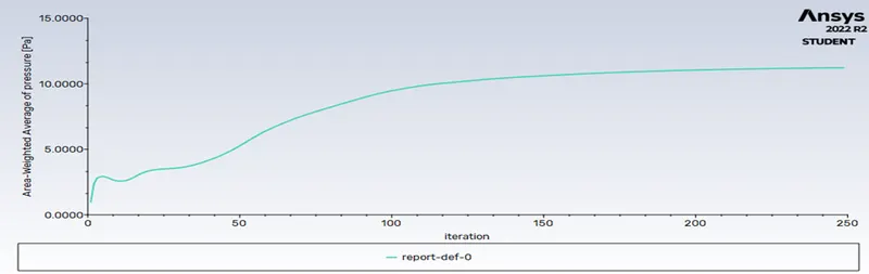
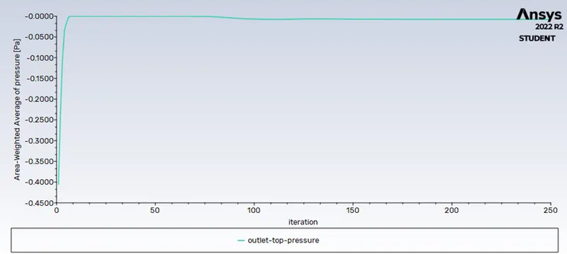
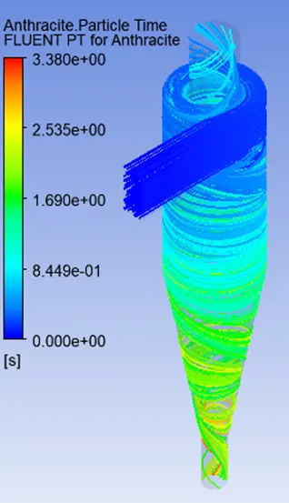
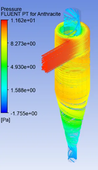
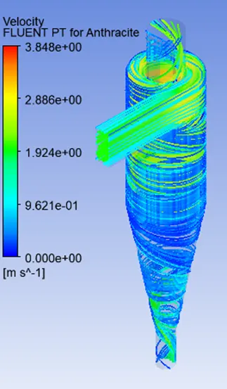
Case2: 2 m/s, 5micrometer(µm)
 |
 |
 |
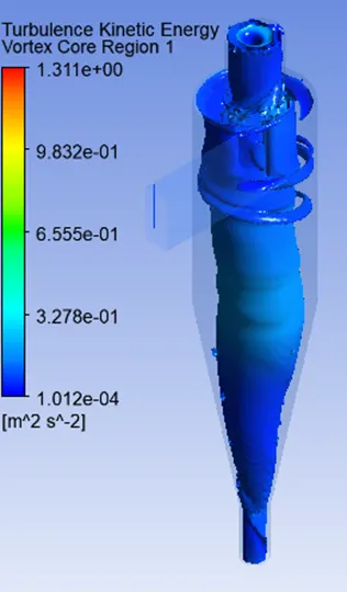 |

Separation Efficiency in % = (290 / 378) * 100
= 76.71 %
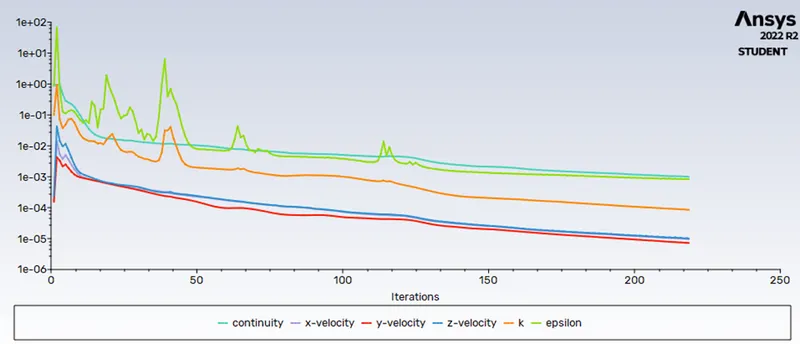
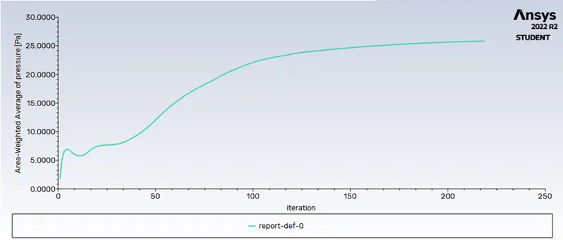
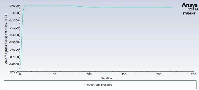
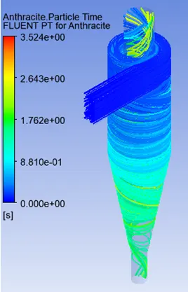
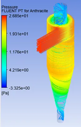
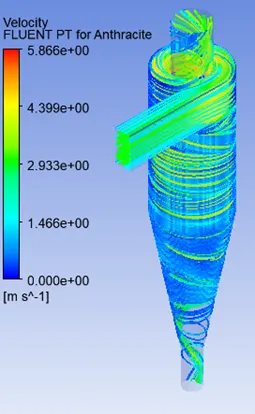
Case2: 3 m/s, 5micrometer(µm)
 |
 |
 |
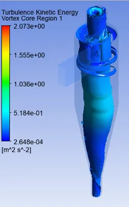 |

Separation Efficiency in % = (247 / 378) * 100
= 65.34 %
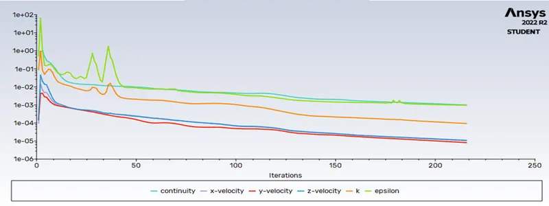
Case2: 4 m/s, 5micrometer(µm)
 |
 |
 |
 |
||

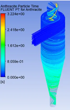
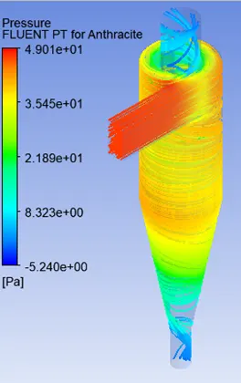
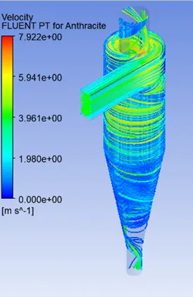
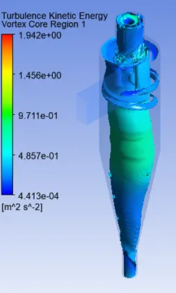
Separation Efficiency in % = (260 / 378) * 100
= 68.78 %
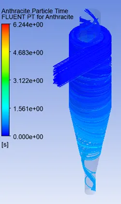
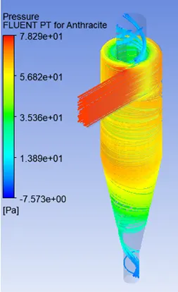
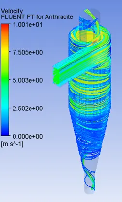
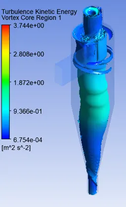
Case2: 5 m/s, 5micrometer(µm)
 |
 |
 |
 |
||

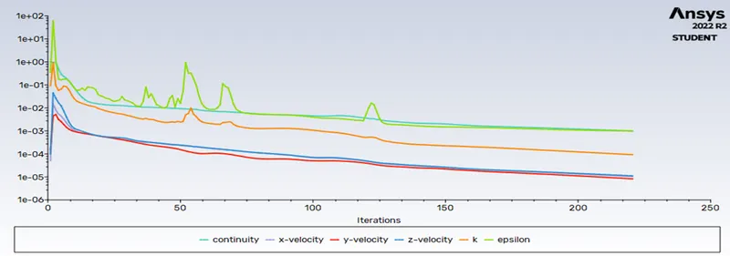
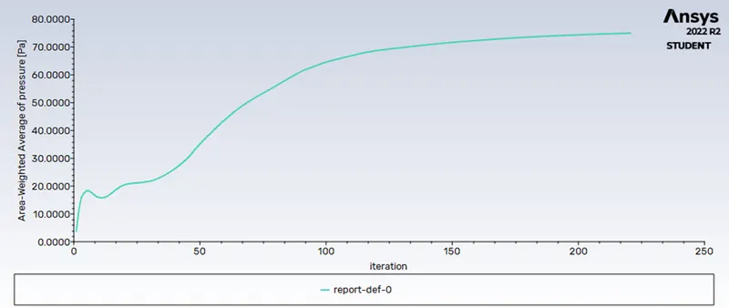
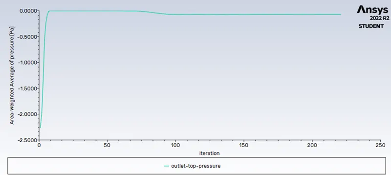
Separation Efficiency in % = (280 / 378) * 100
= 74.07 %
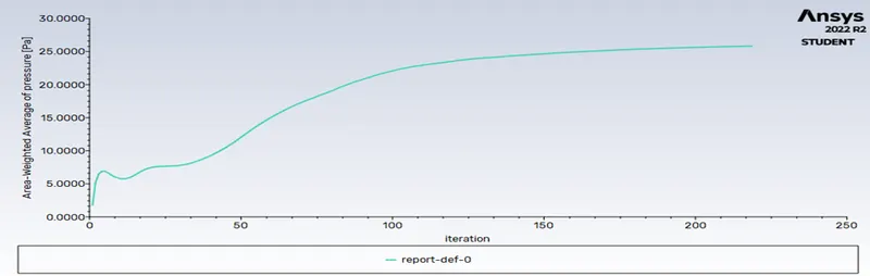
Pressure Drop
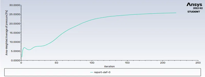
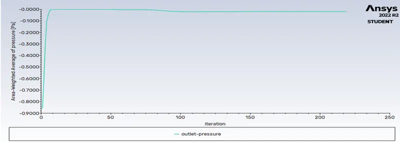
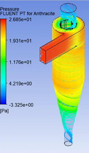
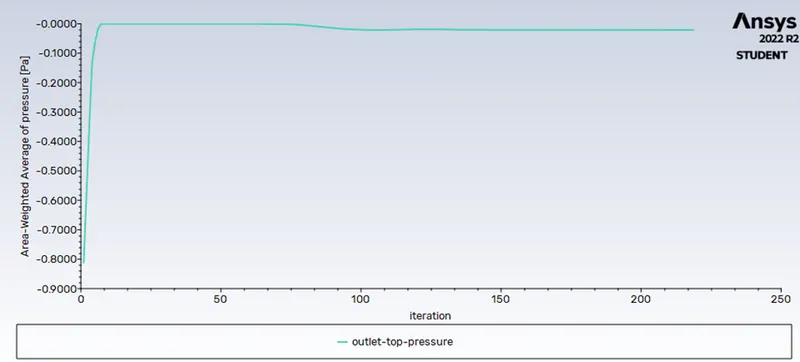
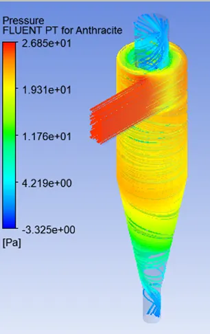
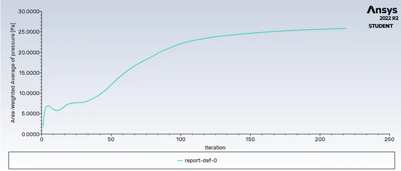
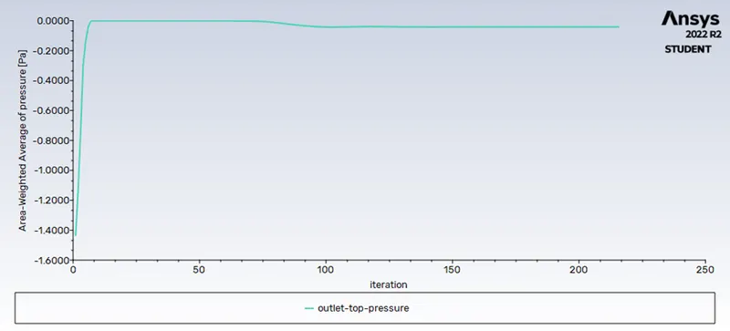
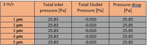
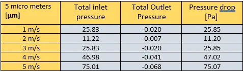
Pressure drops are connected with all cyclone separators. The pressure drop is the amount of energy required to move the gas through the separator, or the amount of resistance introduced to the system flow by the cyclone separator. The pressure drop is determined by the cyclone's gas flow rate, density, and geometry.
Pressure drop = Total inlet pressure - Total Outlet Pressure
Conclusion:
- At a fixed velocity, the separation effectiveness of a cyclone separator increases with particle diameter because the larger the particle diameter, the more its inertia, and hence the possibility of it escaping from the top outlet of the cyclone separator.
- The pressure decrease is related to the cyclone separator's efficiency. Pressure drops are greatest in high-efficiency cyclones.
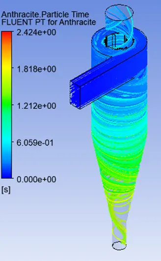
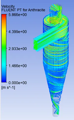
- The higher the velocity, the higher the pressure drop and the higher the efficiency. Also, as particle diameter and velocity rise, so does particle residence time.