Week 8 - Simulating Cyclone separator with Discrete Phase Modelling
Simulating Cyclone separator with Discrete Phase Modelling
Aim:-
- Describe empirical models of cyclone separators.
- Perform analysis on a given cyclone separator model by varying the particle diameter from `1mu m` to `5 mu m` and calculate the separation efficiency for each case.
- Additionally, perform an analysis on a given cyclone separator model by varying the particle velocity from 1m/s to 5m/s and calculate the separation efficiency and pressure drop in each case.
Objective:
- Understand the definition and working of cyclone separator.
- Study of empirical models used to calculate the cyclone separator efficiency.
- Perform geometry defeaturing or extract fluid volume to perform CFD analysis on the model.
- Simulate the model of cyclone separator by varying the particle diameter from `1mu m` to `5mu m` and calculate the separation efficiency.
- Furthermore, simulate the same model for varying velocity from 1m/s to 5m/s and calculate the separation efficiency and pressure drop in each case.
Cyclone Separators
Cyclone separators or simply cyclones are separation devices (dry scrubbers) that use the principle of inertia to remove particulate matter from flue gases.
Cyclone separators is one of many air pollution control devices known as pre-cleaners since they generally remove larger pieces of particulate matter. This prevents finer filtration methods from having to deal with large, more abrasive particles later on.
Working
Cyclone separators work much like a centrifuge, but with a continuous feed of dirty air. In a cyclone separator, dirty flue gas is fed into a chamber. The inside of the chamber creates a spiral vortex, similar to a tornado. This spiral formation and the separation are shown in the below .gif figure.
The lighter components of this gas have less inertia, so it is easier for them to be influenced by the vortex and travel up it. Contrarily, larger components of particulate matter have more inertia and are not as easily influenced by the vortex.
Since these larger particles have difficulty flowing the high-speed spiral motion of the gas and the vortex, the particles hit the inside walls of the container and drop down into a collection hopper. These chambers are shaped like an upside-down cone to promote the collection of these particles at the bottom of the container. The cleaned flue gas escapes out the top of the chamber.
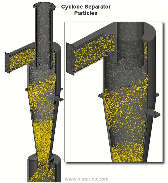
An inaccuracy in cyclone efficiency prediction may result in an inefficient design of cyclone separators. Models to predict the behavior of cyclones are usually empirical. It remains largely a process of trial and error since empirical cyclones models are only applicable to specific cyclone geometries.
Cyclone efficiency empirical models
There are four different cyclone efficiency empirical models, namely - Lapple, Koch and Licht, Li and Wang, and Iozia and Leith.
Iozia and Leith Model
Iozia and Leith (1990) logistic model is a modified version of Barth (1956) model which is developed based on force balance. The model assumes that a particle carried by the vortex endures the influence of two forces: a centrifugal force, Z, and flow resistance, W. Core length, `z_e`, and core diameter, `d_c` are given as
`z_c = (H-S)-[(H-S)/((D/B)-1)][(d_c/B)-1]` for `d_c>B`
`z_c = H-S` for `d_c < B`
`d_c = 0.47(ab/D^2)^-0.25 (D_e/D)^1.4`
The addition made by Iozia and Leith on the original Barth(1956) model is the core length `z_c` and slope parameter β expression which is derivative based on the statistical analysis of experimental data of cyclone with D=0.25m. The collection efficiency `ɳ_i` of particle diameter `d_(p i)` can be calculated from
`ɳ_i = 1/(1+((d_pc)/(bar d))^β`
Where `d_(pc)` is the 50% cut size given by Barth (1956)
`d_pc = [(9mu Q)/(pi p_p Z_p v^2_tamx)]^0.5`
Li and Wang Model
The Li and Wang (1989( model includes particle bounce or re-entrainment and turbulent diffusion at the cyclone wall. A two-dimensional analytical expression of particle distribution in the cyclone is obtained. Li and Wang model was developed based on the following assumptions:
The radial particle velocity and the radial concentration profile are not constant, for uncollected particles within the cyclones.
Boundary conditions with the consideration of turbulent diffusion coefficient and particle bounce re-entrainment on the cyclone wall are:
`c = c_0`, at `theta=0`
`D_r (del c)/(del r) = (1-alpha)wc`, at `r = D/2`
The tangential velocity is related to the radius of cyclone by:
`uR^n =` constant
The concentration distribution is a cyclone is given as:
`c(r,theta) = (c_0(r_w-r_n)exp{-lambda[1/K(1+n) r^(1+n)]})/(int_(r_n)^(r_w) exp{1/(K(1+n)) r^1+n}dr`
Where
`k = ((1-n)(rho_p-rho_g)d^2Q)/(18mub(r_w^(1-n)-r_n^(1-n)))`
And
`lambda=((1-alpha)kw_w)/D_r r^n_w`
The resultant expression of the collection efficiency for the particle of my size is given as
`eta_i = 1-exp{-lambda theta_1}`
Where
`theta_1 = 2 pi(S+L)/a`
Koch and Lich model
Koch and Licht (1977) collection theory recognized the inherently turbulent nature of cyclones and the distribution of gas residence times within the cyclone. Koch and Licht describe particle motion in the entry and collection regions with the additional following assumptions:
The tangent velocity of a particle is equal to the tangential velocity of the gas flow, i.e. there is no slip in the tangential direction between the particle and the gas.
The tangential velocity is related to the radius of cyclone by:
`uR^n =` constant.
A force balance and an equation on the particles collection yields the grade efficiency `eta_i`
`eta_i = 1-exp{-2[(G tau_I Q)/(D^3) (n+1)]^(0.5/(n+1))}`
Where,
`G = (8k_c)/(K_a^2 K_b^2)`
`n = 1-{1-((12D)^0.14)/2.5}{(T+460)/530}^0.3`
`tau_i =( rho_p d^2_(pi))/(18mu)`
G is a factor related to the configuration of the cyclone, n is related to the vortex and tau is the relaxation term.
Lapple Model
Lapple (1951) model was developed based on force balance without considering th4e flow resistance. Lapple assumed that a particle entering the cyclone is evenly distributed across the inlet opening. The particle that travels from the inlet half-width to the wall in the cyclone is collected with 50% efficiency. The empirical relationship developed by Lapple (1951) to calculate a 50% cut diameter, `d_(pc)`, is
`d_(pc) = [(9mub)/(2piN_e v_i(rho_p-rho_g))]^(1/2)`
Where `N_e` is the number of revolutions
`N_e = 1/a[h+(H-h)/2]`
The efficiency of collection of any size of the particle is given by
`eta_i = 1/(1+(d_(pc)/(hat d_(pi)))`
Problem Setup
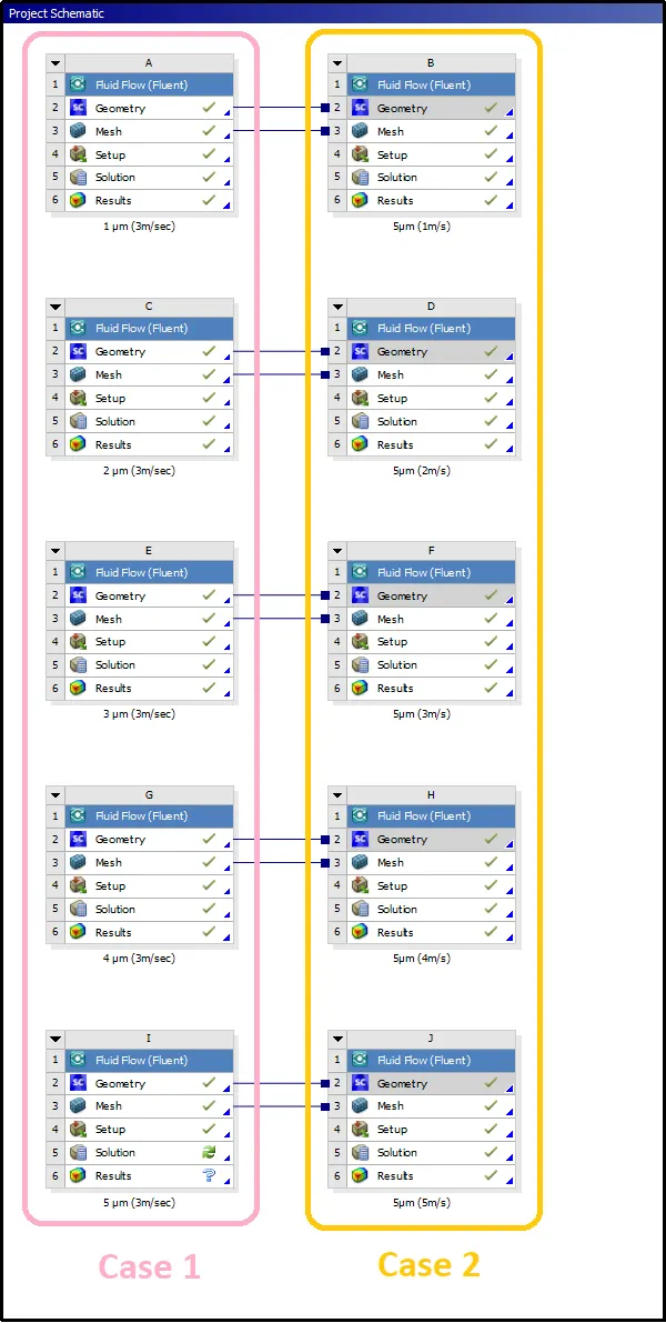
In this project, the simulation in the first case was performed for varying the diameter from `1mu m` to `5 mu m` for the constant velocity of 3m/s and in case 2 the problem was simulated considering particle diameter size as `5 mu m` for all simulations with varying particle velocity from 1m/sec to 5m/sec.
Geometry setup
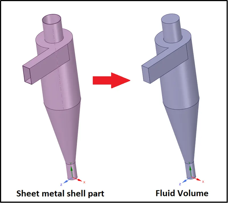
Before simulation is vital to extract the fluid volume for the CFD simulations, therefore, the geometry was loaded in the space claim. The fluid volume inside the Cyclone separators was extracted by using an edge selection process. Inlet and both lower and upper outlet edges were used to define the boundary area of the fluid volume.
Boundary definition:
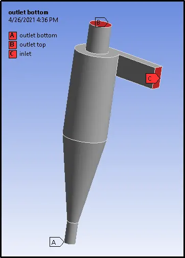
In boundary definition inlet and two outlets are defined as shown in the below picture. Fluent automatically considers other walls of the Cyclone separators in a fluent setup.
Meshing:
For the meshing of the fluid volume cutcell meshing approach is preferred for this particular simulation. Structural mesh gives the best results for current problems.
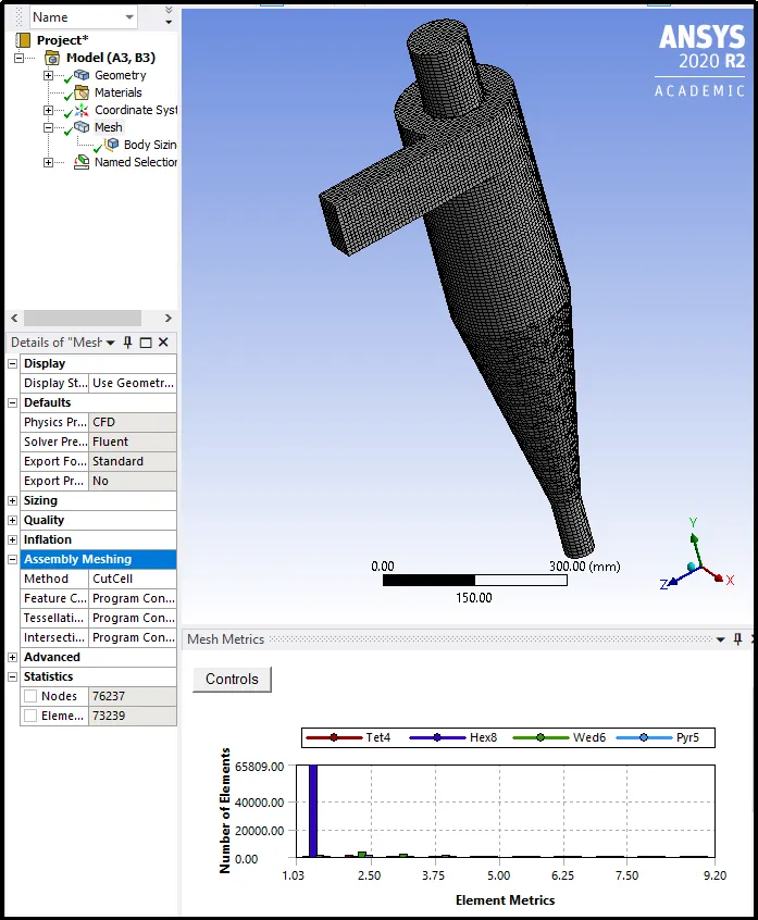
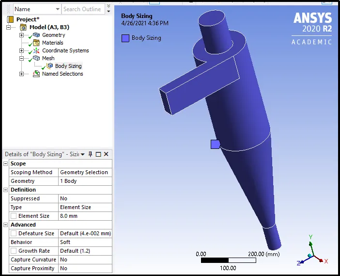
Element size set to 8mm. It is a very important factor to define the maximum number of particles in the simulation.
Fluent setup
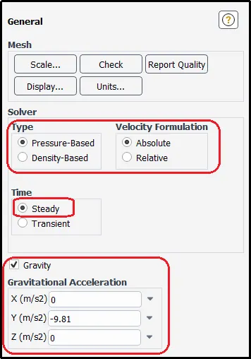
For this study solver type is considered pressure-based with velocity formulation as absolute. Solution simulated as steady-state simulation.
The gravity option was turned on and gravitational acceleration is taken as 9.81 in the negative y-direction.
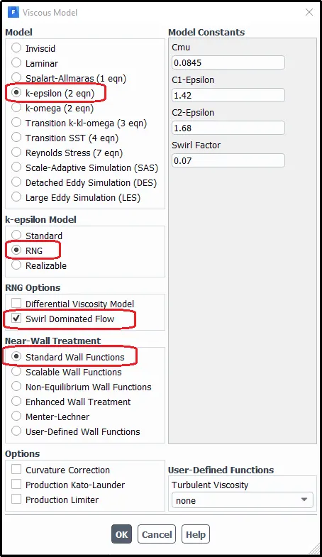
Turbulent model k-epsilon was considered with RNG to capture vortex flow properly. The swirl dominant option was also turned on by considering standard wall function.
Discrete Phase modeling (DPM)
To carry out this type of simulation one has to use Discrete Phase modeling (DPM). DPM preferred to represent solid particles are present in gas or liquid, liquid droplets in the gas, and, sometimes, bubbles in the liquid while performing CFD simulations.
In DPM, we can consider two phases - one is called the continuous phases and the other is called the discrete phase. The former phase consists of a fluid that is flowing within the fluid volume. And the latter phase consists of the smaller particle that is supposed to be interacting with the former phase. The discrete phase can also exchange momentum, mass, and energy with the fluid phase or the continuous phase in the current case.
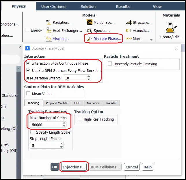
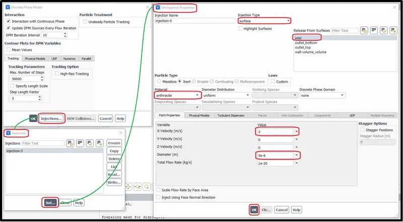
In injection parameters, particle size (diameter) and velocity was provided at the inlet
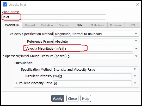
Boundary condition
Inlet
Inlet velocity was set up the same as particle velocity
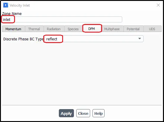
For the inlet, the DPM (Discrete Phase Model) set up as reflect so that the particle does not come out from the inlet wall.
Cyclone separator wall
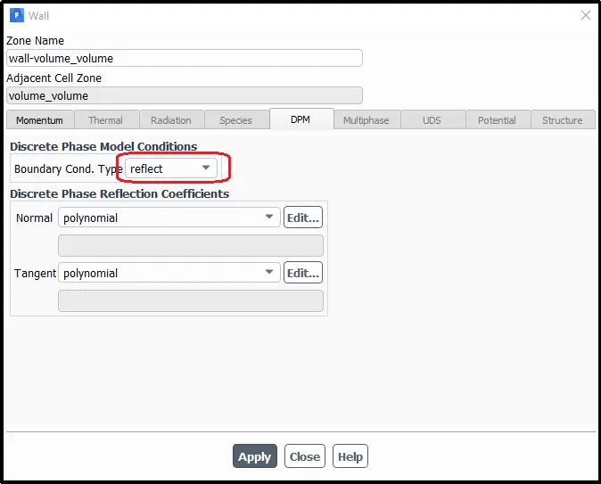
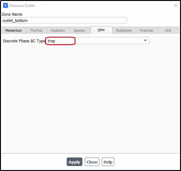
Outlet Bottom
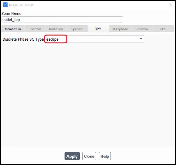
Outlet Top
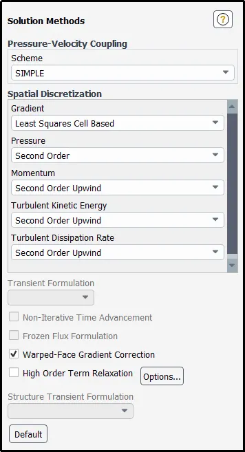
Solution Method
The solution method was set to simple with the second-order upwind scheme for all equations.
Solution Initialization
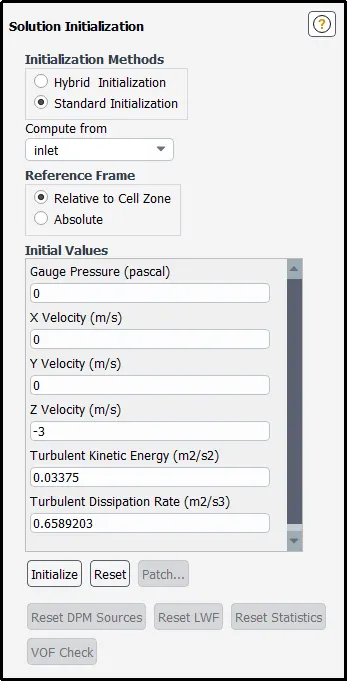
Solution setup was initialized by using standard initialization process as in this problem all surfaces boundary is already defined. The solution was initialized from the inlet.
Solution Convergence
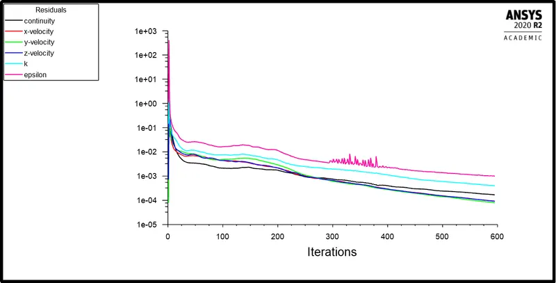
Solution set to run for 1000 iteration but it converging at 595th iteration. The following plot shows the residual plot for the above simulation. The residual plot that appearing from all simulations of both cases are almost identical to one another.
CASE-1
For Particle Diameter 1μm (Velocity 3m/s)
DPM Iteration ....

number tracked = 120, escaped = 53, trapped = 27, incomplete = 40 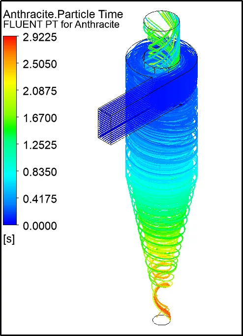
For Particle Diameter 2μm (Velocity 3m/s)
DPM Iteration ....

number tracked = 120, escaped = 49, trapped = 71 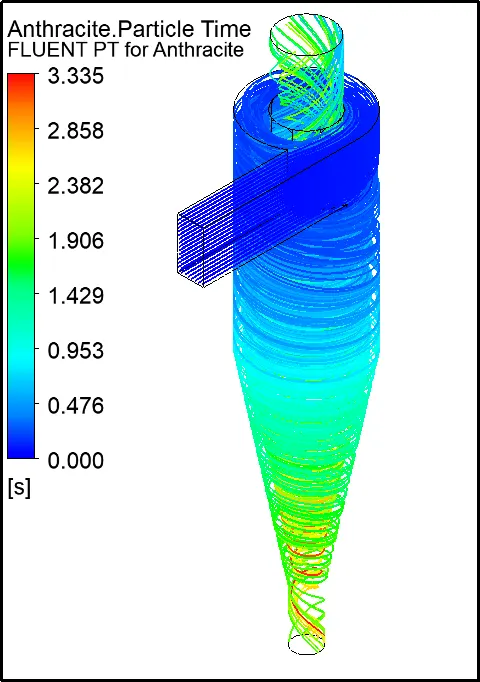
For Particle Diameter 3μm (Velocity 3m/s)
DPM Iteration ....

number tracked = 120, escaped = 41, trapped = 75, incomplete = 4 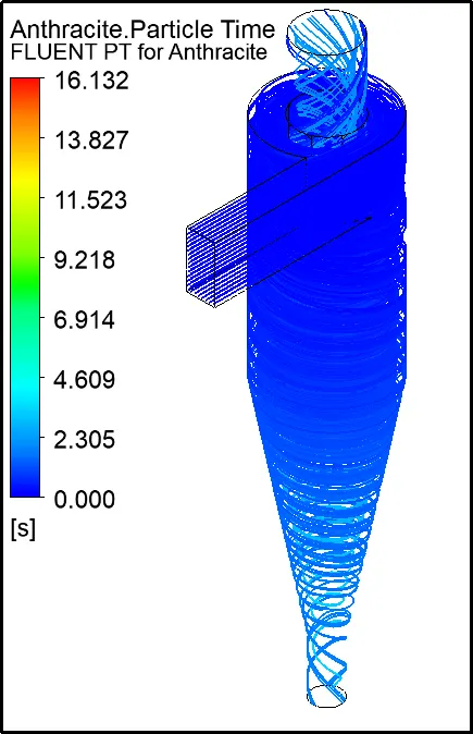
For Particle Diameter 4μm (Velocity 3m/s)
DPM Iteration ....

number tracked = 120, escaped = 12, trapped = 103, incomplete = 5 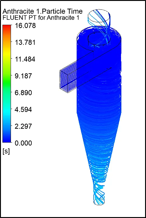
For Particle Diameter 5μm (Velocity 3m/s)
DPM Iteration ....

number tracked = 120, escaped = 3, trapped = 116, incomplete = 1 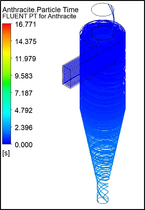
Separation Efficiency
The separating efficiency of a cyclone separator used for removing solid particles from a gas stream (for example ash particles from the combustion gas which is passed to a gas turbine) is increased by retarding the particles before they arrive at the cyclone and thereafter accelerating them over a short distance before they enter the cyclone.
Several factors can affect a cyclone separator's efficiency. These include particle density, particle size, volumetric flow rate, pressure drop, cone length, body length, the ratio of accepting port to body diameter, and even the smoothness of the cyclone’s internal surfaces.
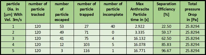
Observation from the above table portrays the fact that the separation efficiency increases as the diameter of the particle increases. Large diameter particles have a large mass which traps the particle at the bottom outlet hence the separation efficiency increases with the rise in particle size. Moreover, particle size does not affect pressure drop therefore pressure drop is the same for all the simulations.
CASE-2
For Particle Diameter 5μm (Velocity 1m/s)
DPM Iteration ....

number tracked = 120, escaped = 21, trapped = 13, incomplete = 86 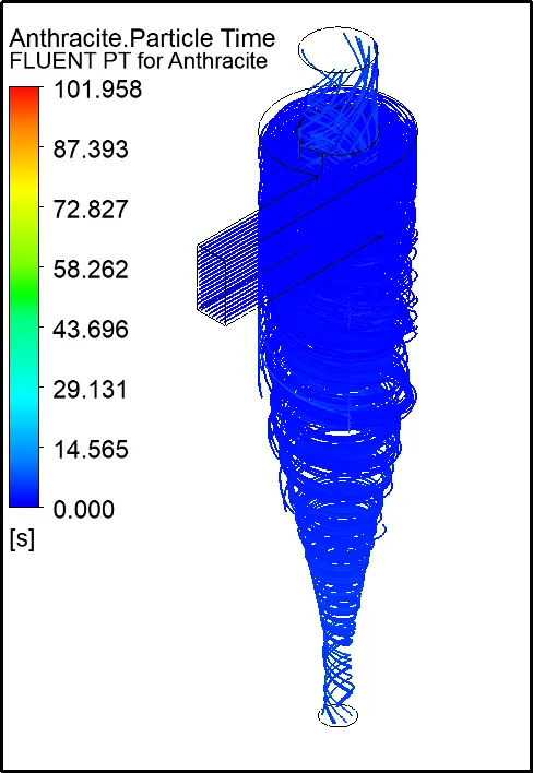
For Particle Diameter 5μm (Velocity 2m/s)
DPM Iteration ....

number tracked = 120, escaped = 18, trapped = 40, incomplete = 62 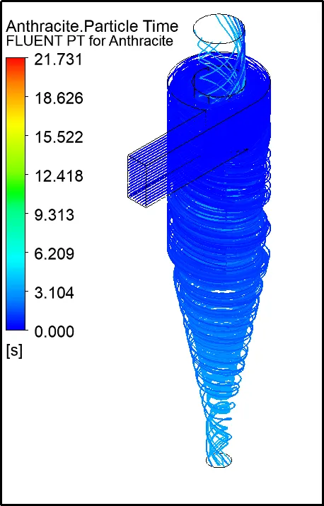
For Particle Diameter 5μm (Velocity 3m/s)
DPM Iteration ....

number tracked = 120, escaped = 3, trapped = 116, incomplete = 1
For Particle Diameter 5μm (Velocity 4m/s)
DPM Iteration ....

number tracked = 120, escaped = 4, trapped = 116 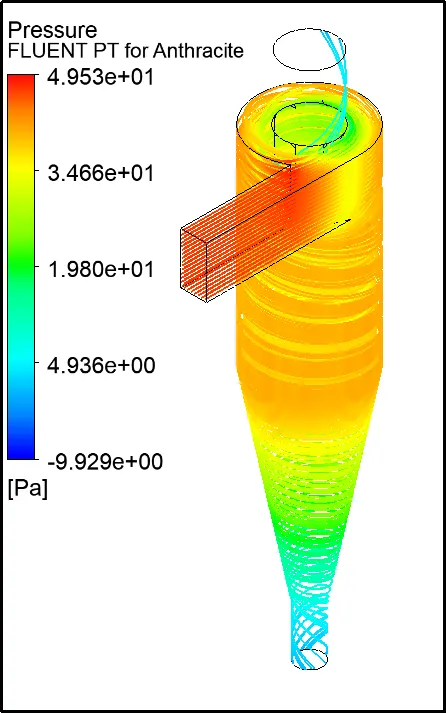
For Particle Diameter 5μm (Velocity 5m/s)
DPM Iteration ....

number tracked = 120, escaped = 5, trapped = 115 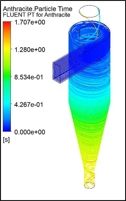
Pressure Drop
All cyclone separators have an associated pressure drop. The pressure drop can be thought of as the amount of energy required to move the gas through the separator, alternatively, it can be thought of as the amount of resistance the cyclone separator adds to the system flow. The pressure drop is a product of the gas flow rate, gas density, and cyclone geometry. Pressure drop can be expressed as:
DR = Ra inlet - Ra outlet
Where:
DR = Cyclone Pressure Drop
Ra = Absolute Pressure
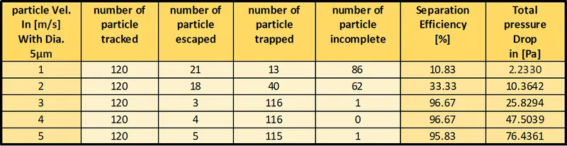
From the observation table of case2, we can say that the separation efficiency increases as the velocity increases. Furthermore, pressure drop also increases with the increase in velocity.
Conclusion:-
The larger the particle size, the higher the separation efficiency and vice versa.
Also, as the velocity at the inlet increases the separation efficiency increases.
The higher the velocity at the inlet leads to more pressure drop in the cyclone separator.
References:-
[1] Cyclone separator -https://energyeducation.ca/encyclopedia/Cyclone_separator#:~:text=Cyclone%20separators%20or%20simply%20cyclones,larger%20pieces%20of%20particulate%20matter.
[2] Evolution on empirical models for the prediction of cyclone efficiency -https://www.academia.edu/2893863/Evaluation_on_empirical_models_for_the_prediction_of_cyclone_efficiency
[3] Cyclone separator working principle - Cyclone Separator Working Principle (Dust Separator) Explained - saVRee
[4] Numerical study of gas-solid flow in a cyclone separator -https://www.sciencedirect.com/science/article/pii/S0307904X06000291
[5] A CFD Study on the Prediction of Cyclone Collection Efficiency - https://www.researchgate.net/publication/232747389_A_CFD_Study_on_the_Prediction_of_Cyclone_Collection_Efficiency