Week 8 - Simulating Cyclone separator with Discrete Phase Modelling
Aim:
To perform analysis on cyclone separator and calculate the separation efficiency and pressure drop.
Objective:
To write a few words about any four empirical models used to calculate the cyclone separator efficiency.
To perform an analysis on a given cyclone separator model by varying the particle diameter from 1 μm to 5 μm and calculate the separation efficiency in each case. Discuss the results. [Use both the velocity's as 3m/sec.]
To perform an analysis on a given cyclone separator model by varying the particle velocity from 1 m/sec to 5 m/sec and calculate the separation efficiency and pressure drop in each case. Discuss the results. [Use particle diameter size as 5 μm for all cases & keep flow velocity same as particle velocity]
Boundary Conditions:
Inlet and wall: Reflect
Outlet (Top): Escape
Outlet (Bottom/dustbin): Trap
Cyclone Separator:
Cyclone separators are separation devices that use the principle of inertia to remove particulate matter from flue gases. Cyclone separator is one of many air pollution control devices known as pre-cleaners since they generally remove larger pieces of particulate matter. This prevents finer filtration methods from having to deal with large, more abrasive particles later on. In addition, several cyclone separators can operate in parallel, and this system is known as a multi-cyclone.
It is important to note that cyclones can vary drastically in their size. The size of the cyclone depends largely on how much flue gas must be filtered; thus larger operations tend to need larger cyclones. For example, several different models of one cyclone type can exist, and the sizes can range from a relatively small 1.2-1.5 meters tall (about 4-5 feet) to around 9 meters (30 feet)—which is about as tall as a three-story building.
Working:
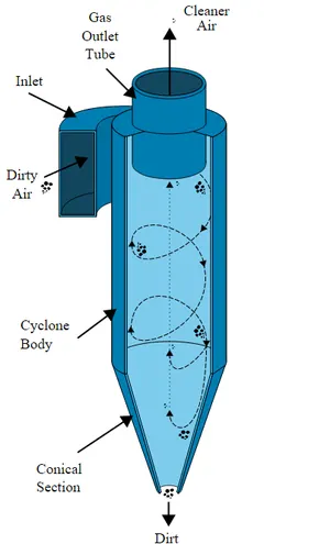
Cyclone separators work much like a centrifuge, but with a continuous feed of dirty air. In a cyclone separator, dirty flue gas is fed into a chamber. The inside of the chamber creates a spiral vortex, similar to a tornado. This spiral formation and the separation is shown in the Figure below. The lighter components of this gas have less inertia, so it is easier for them to be influenced by the vortex and travel up it. Contrarily, larger components of particulate matter have more inertia and are not as easily influenced by the vortex.
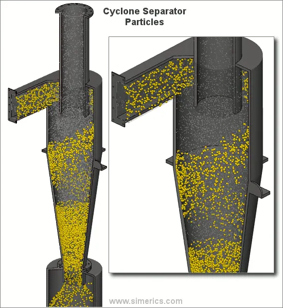
Most cyclones are built to control and remove particulate matter that is larger than 10 micrometres in diameter. However, there do exist high-efficiency cyclones that are designed to be effective on particles as small as 2.5 micrometres. As well, these separators are not effective on extremely large particulate matter. For particulates around 200 micrometres in size, gravity settling chambers or momentum separators are a better option.
Out of all the particulate-control devices, cyclone separators are among the least expensive. They are often used as a pre-treatment before the flue gas enters more effective pollution control devices. Therefore, cyclone separators can be seen as "rough separators" before the flue gas reaches the fine filtration stages.
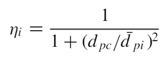
- Iozia and Leith Model
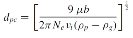
The model assumes that a particle carried by the vortex endures the influence of two forces: a centrifugal force and a flow resistance. The collection efficiency of particle diameter dpi can be calculated from
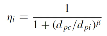
dpc is the cut-diameter given by
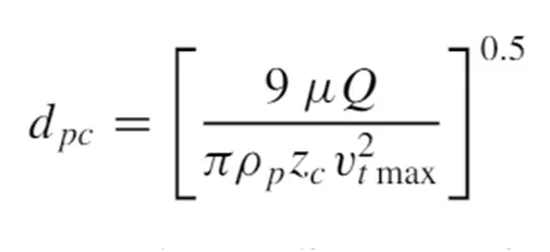
The cut diameter of the cyclone is defined as the size of the particles collected with 50% collection efficiency.
- Li and Wang model
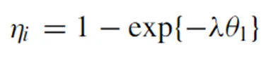
This model includes particle bounce and turbulent diffusion at the cyclone wall.
The radial particle velocity and the radial concentration profile are variable for uncollected particles within the cyclone.
The tangential velocity is related to the radius of cyclone by uR^n = constant.
- Koch and Licht model
The Kock and Licht collection theory recognized the inherently turbulent nature of the cyclones and the distribution of gas residence times within the cyclone. Following assumptions were used to describe the particle motion in the entry and collection regions.
The tangential velocity of a particle is equal to the tangential velocity of the gas flow i.e., there is no slip in the tangential direction between the particle and the gas.
The tangential velocity is related to the radius of cyclone by uR^n = constant.
- Lapple
This model was developed without considering the flow resistance. Lapple assumed that a particle entering the cyclone is evenly distributed across the inlet opening. The particle that travels from inlet half width to the wall in the cyclone is collected with 50% efficiency. The 50% cut diameter and the collection efficiency are given by, half width to the wall in the cyclone is collected with 50% efficiency. The 50% cut diameter and the collection efficiency are given by,
GEOMETRY & MESH:
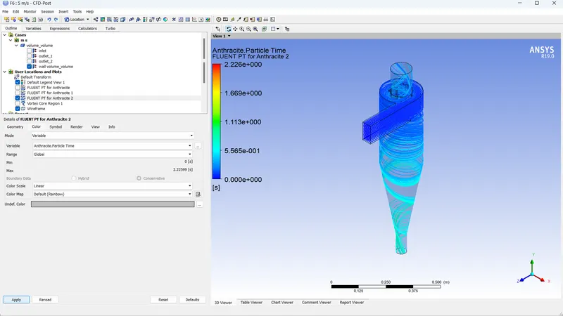
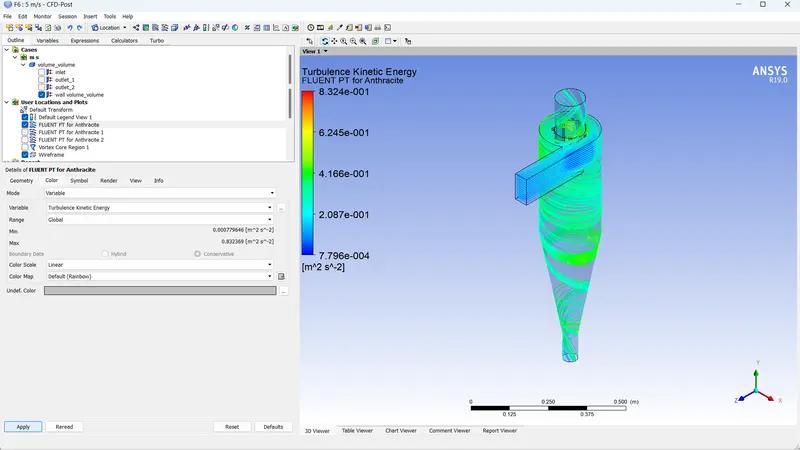
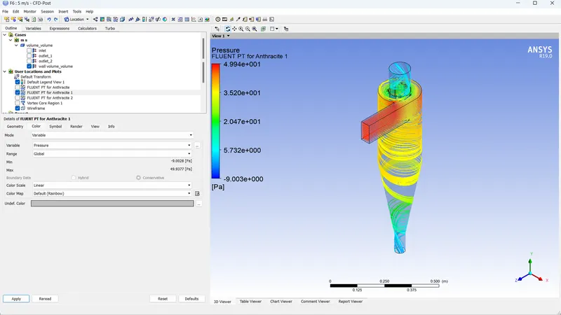
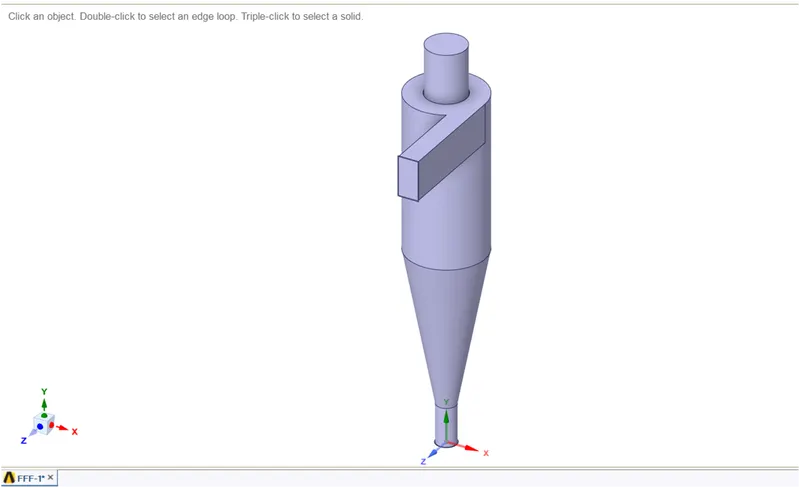
The model has a tangential entry duct at the top through which particle laden gas enters the separator. There are two outlets, one at the top & other at the bottom. Particles are trapped in the bottom outlet whereas gas escapes through the top outlet. The vortex is generated in the barrel & the cone.
MESH:
- Element size: 10 mm
- Body fitted Cartesian: 10 mm
- The face selecting tool is selected. The inlets, outlet1 (top) and outlet2 (bottom) is named. The inlet is through which the particles enter the lighter impurities escape through the top, and the heavier impurities are trapped in the bottom.
Solving:
General conditions:
- This analysis involves the orientation of the cyclone separator. As it is in the x-y plane, the acceleration due to gravity needs to be turned on. As acceleration due to gravity acts upwards, the g value is assigned as -9.81 in the positive y axis.
- Pressure based solver is used. Steady state analysis is done and the velocity formulation is normal to the boundary and absolute.
Physics set up:
- Turbulence modelling:
- The K-epsilon (2 equation) model with RNG and swirl dominated flow is selected. The wall mofunctions are standard wall functions.
- Since temperature is not involved, the Energy is not turned on.
DPM:
- Discrete phase modelling is opted for.
- The model is enabled for interaction with the continuous phase. DPM interval level is 10.
- For injection, the particle type is inert. From fluent database, anthracite is selected. It is released from the inlet, with velocity in the x-direction being 3m/s. This velocity may be manipulated further. The particle diameter chosen for the first analysis is one micrometre. The particle diameter is varied from one micrometre to five micrometre to calculate the separation efficiencies.
Boundary conditions:
- The boundary conditions are provided to three named selections, inlet, outlet (1) top and outlet (2) bottom.
- For inlet, the momentum conditions are v3locity is 3m/s in the x direction, being absolute and normal to the boundary. The DPM condition is reflect. This signifies that the particles are not allowed to escape or get trapped in the inlet.
- For the top outlet, the Momentum condition is basically pressure condition, The DPM condition is escape. Particles can escape from this Boundary
- The bottom outlet is also a pressure outlet, with the DPM condition being trap.
Initialization:
- Standard initialization is done with flow from inlets.
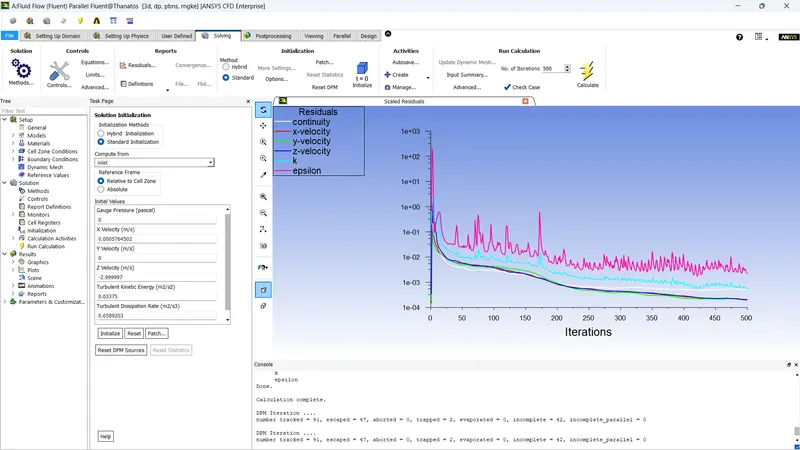
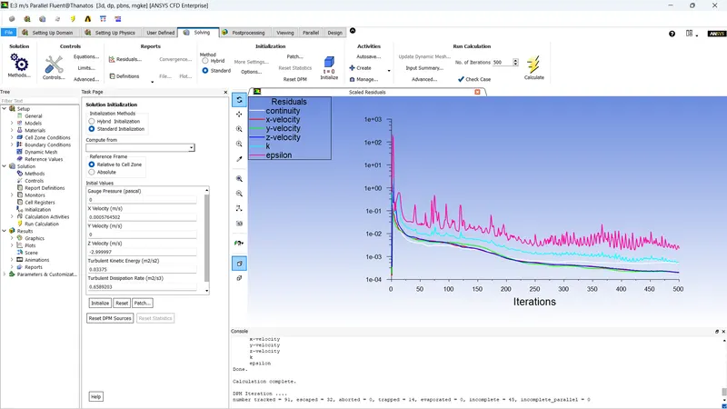
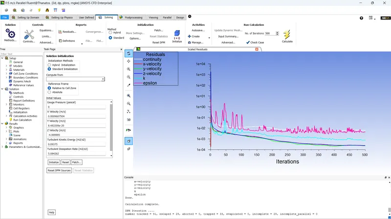
- The analysis is done for 500 iterations.
RESULT:
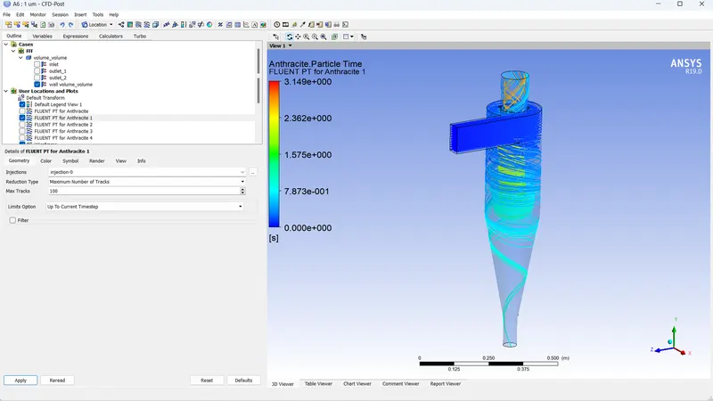
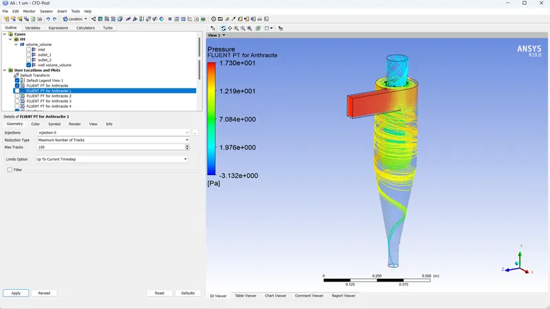
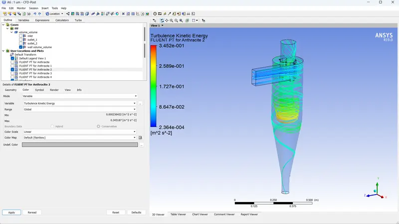
CASE 1:
- Diameter of the particles = 1 micrometres
The scaled residuals plot:
Post processing:
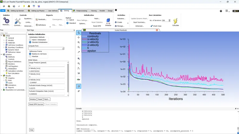
- Diameter of the particles = 3 micrometres
The scaled residuals plot:
Post processing:
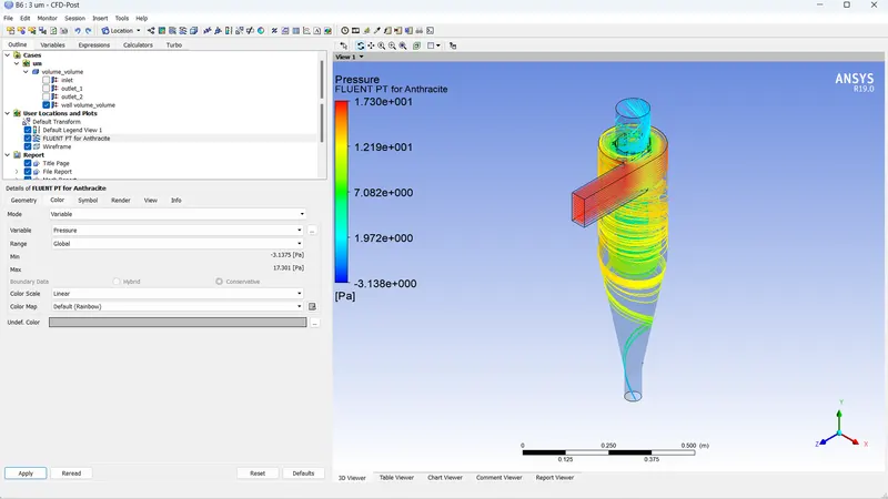
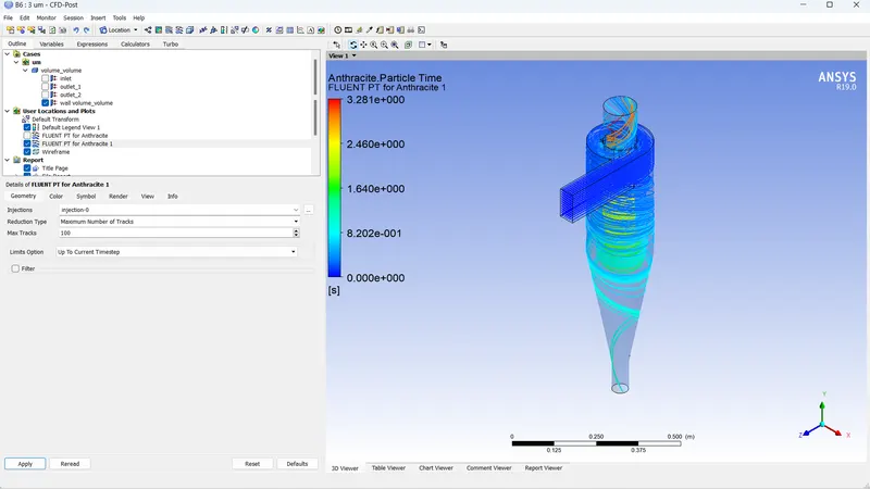
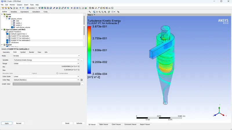
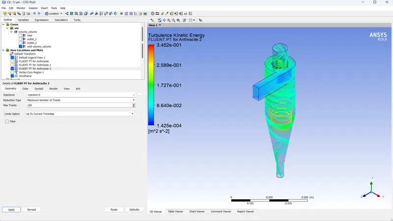
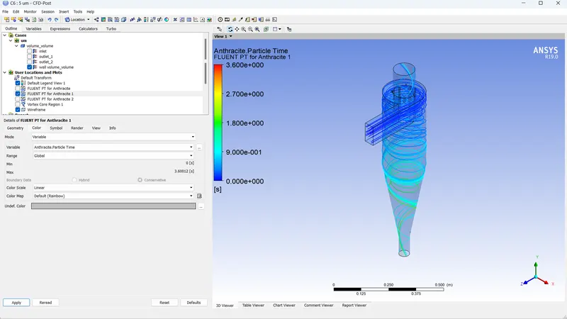
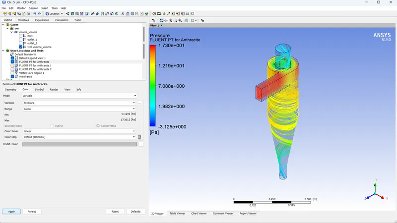
- Diameter of the particles = 5 micrometres
The scaled residuals plot:
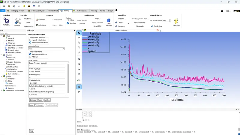
Post processing:
CASE 2:
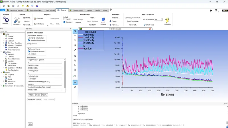
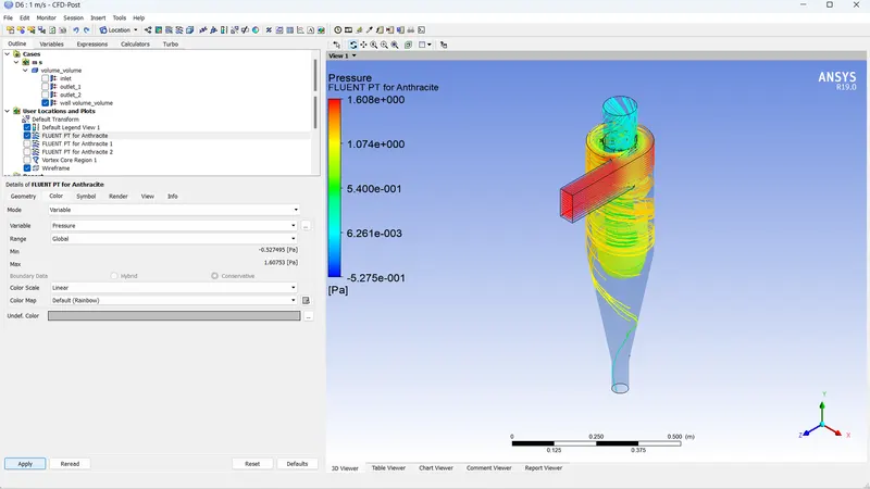
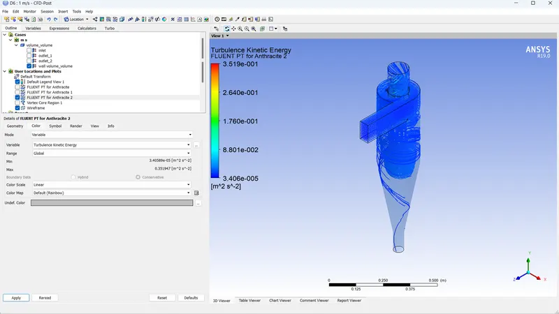
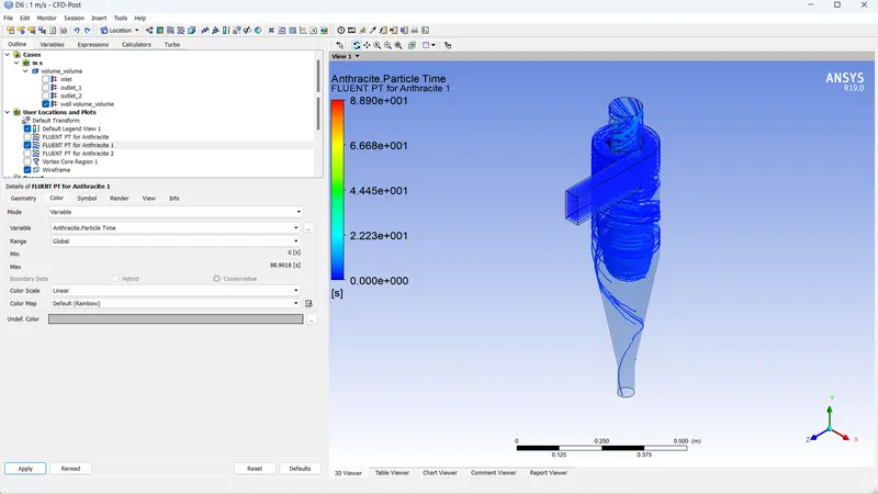
- inlet velocity = 1m/s, Diameter of particle = 5e-6
Residual:
Post processing:
- inlet velocity = 3m/s, Diameter of particle = 5e-6
Residual:
Post processing:
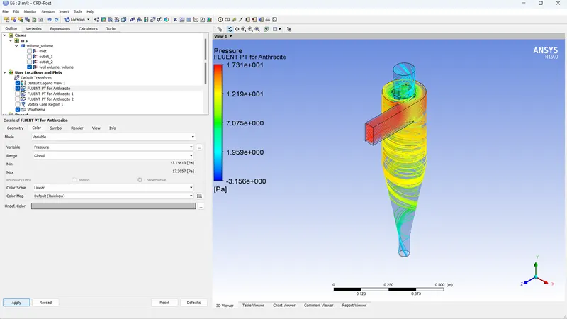
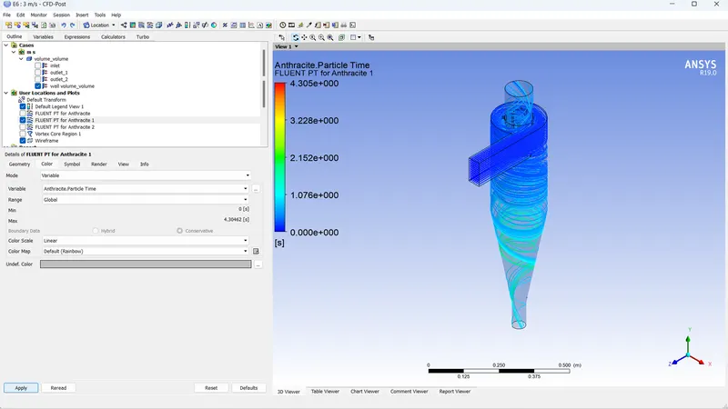
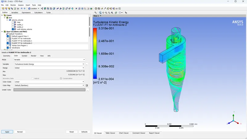
- inlet velocity = 5m/s, Diameter of particle = 5e-6
Residual:
Post processing: