Week 8 - Simulating Cyclone separator with Discrete Phase Modelling
AIM
To perform analysis on cyclone separator and calculate the separation efficiency and pressure drop.
Objective:-
- To write a few words about any four empirical models used to calculate the cyclone separator efficiency.
- To perform an analysis on a given cyclone separator model by varying the particle diameter from 1 μm to 5 μm and calculate the separation efficiency in each case. Discuss the results. [Use both the velocity's as 3m/sec.]
- To perform an analysis on a given cyclone separator model by varying the particle velocity from 1 m/sec to 5 m/sec and calculate the separation efficiency and pressure drop in each case. Discuss the results. [Use particle diameter size as 5 μm for all cases & keep flow velocity same as particle velocity]
Boundary Conditions:-
Inlet and wall:- Reflect
Outlet(Top):- Escape
Outlet(Bottom/dustbin) - Trap
PROCEDURE
To write a few words about any four empirical models used to calculate the cyclone separator efficiency.
- Cyclone separators are separation tools that filter flue gases by removing particle matter using the law of inertia. The term "pre-cleaner" refers to a variety of air pollution management technologies that often remove larger bits of particulate matter. One such technology is the cyclone separator.
- This avoids the need for later, finer filtration techniques to handle larger, more abrasive particles. A multi-cyclone system is one that allows many cyclone separators to run simultaneously.
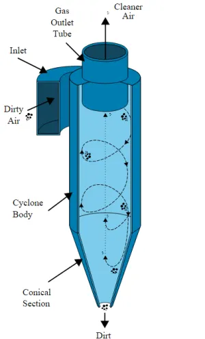
- It's crucial to remember that cyclone sizes can vary greatly. The amount of flue gas that needs to be filtered heavily influences the cyclone's size, hence larger operations typically require larger cyclones.
- For instance, there may be multiple versions of the same type of cyclone, with heights ranging from a relatively tiny 1.2 to 1.5 metres (about 4-5 feet) to about 9 metres (30 feet), which is roughly the height of a three-story skyscraper.
Working:
- Similar to a centrifuge, cyclone separators operate by continuously supplying unclean air. The unclean flue gas is routed into a chamber of a cyclone separator.
- The chamber's inside generates a spiral vortex that resembles a tornado. The figure below depicts this spiral creation and the separation. It is simpler for the lighter parts of this gas to be impacted by the vortex and move up it since they have less inertia.
- Larger particles, on the other hand, have more inertia and are less susceptible to the vortex's influence.
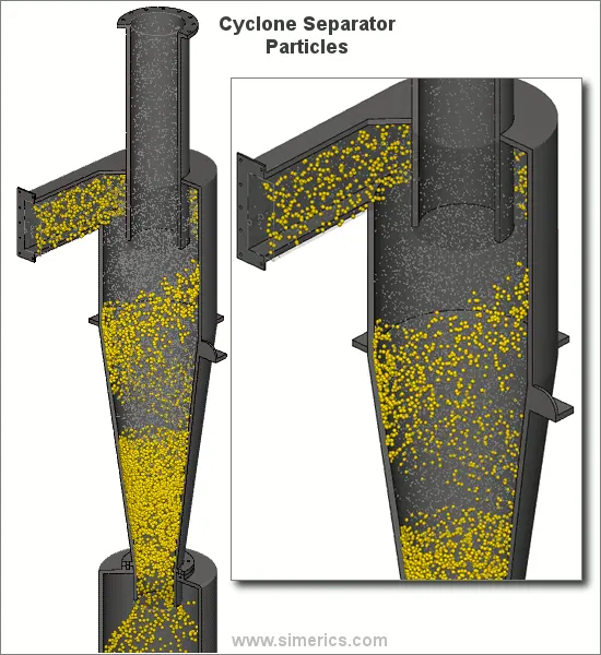
- The majority of cyclones are designed to contain and eliminate particles larger than 10 micrometres in diameter. High-efficiency cyclones that are made to be efficient on particles as small as 2.5 micrometres do exist, though. Furthermore, these separators do not work effectively with very large particle matter. Momentum separators or gravity settling chambers are preferable for particulates less than 200 micrometres.
- Cyclone separators are among the most affordable particle control equipment. Before the flue gas enters more effective pollution control equipment, they are frequently utilised as a pre-treatment. Therefore, before the flue gas enters the fine filtration stages, cyclone separators can be thought of as "rough separators."
Effectiveness:
- Most of the particulate matter in the flue gas may be removed by cyclone separators, which can do so between 50 and 99% of the time.
- The size of the particles has a significant impact on how effectively the cyclone separators can remove this material.
- Less of these particles can be sorted out when there is a lot of lighter particulate matter present.
- Because of this, cyclone separators perform at their best with flue gases that have a lot of large particle matter present.
- Using cyclone separators has a number of benefits and drawbacks. Cyclone separators are advantageous in the first place since they don't require much maintenance and are inexpensive to install.
- This lowers the cost of operation and maintenance. Second, it is easier to dispose of the removed particle matter since it is gathered when it is dry. Last but not least, these units don't take up much room. Utilizing cyclone separators has drawbacks despite being effective. mostly due to the conventional models' inability to efficiently gather particles smaller than 10 micrometres and the machines' poor ability to handle sticky or gooey materials
Empherical models for the effectiveness of cyclone separators:
IOZIA AND LEITH MODEL:
- The logistic model created by Iozia and Leith (1990) is a modified version of the Barth (1956) model and is based on force balance.
- The model presupposes that a particle carried by the vortex experiences the effects of two forces: flow resistance, or W, and centrifugal force, or Z. Core diameter dc and length zc of the core are provided.
zc=(H-S)-H-S(DB)-1[(dcB)-1]">zc=(H−S)−H−S(DB)−1[(dcB)−1]zc=(H-S)-H-S(DB)-1[(dcB)-1] for dc>B
zc=H-S">zc=H−Szc=H-Sfor dc
dc=0.47D(abD2)-0.25(DeD1.4)">dc=0.47D(abD2)−0.25(DeD1.4)dc=0.47D(abD2)-0.25(DeD1.4)
The core length zc and slope parameter expression, which are additions made by Iozia and Leith to the original Barth (1956) model, are developed based on the statistical analysis of experimental data of cyclone with D = 0.25 m. One can determine the collecting effectiveness I of particle diameter dpi from

LI AND WANG MODEL:
- The Li and Wang (1989) model takes into account turbulent diffusion at the cyclone wall as well as particle bounce or re-entrainment.
- It is possible to express the particle distribution in the cyclone analytically in two dimensions. The following presumptions served as the foundation for the Li and Wang model
For uncollected particles inside the cyclones, the radial particle velocity and the radial concentration profile are not constant.
The following are the boundary conditions when the turbulent diffusion coefficient and particle bounce re-entrainment on the cyclone wall are taken into account:
c=c0>r=D2">c=c0>r=D2c=c0>r=D2
Dr(∂c∂r)=(1-α)ωc">Dr(∂c∂r)=(1−α)ωcDr(∂c∂r)=(1-α)ωcat
The tangential velocity and cyclone radius are connected by:
uRn=constant">uRn=constantuRn=constant
The following is the concentration distribution in a cyclone:

The resultant expression of the collection efficiency for a θ1=2π(S+La)">θ1=2π(S+La)θ1=2π(S+La)particle of our size is given as
ηi=1−exp{−λθ1}">ηi=1−exp{−λθ1}ηi=1−exp{−λθ1}
where,
θ1=2πS+La">θ1=2πS+Laθ1=2πS+La
LAPPLE MODEL:
- The force balance-based Lapple (1951) model was created without taking the flow resistance into account.
- Lapple made the supposition that a particle entering the cyclone is dispersed uniformly over the inlet hole.
- In the cyclone, the particle that moves from the entrance half-width to the wall is gathered with a 50% efficiency. In order to calculate a 50% cut diameter, dpc, Lapple (1951) devised a semi-empirical relationship.
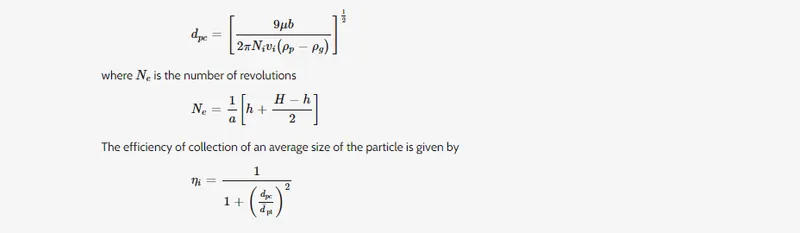
The result section calculates the separation efficiency based on this model and compares it to the experimental results for 5 micrometre at 3 m/s.
GEOMETRY
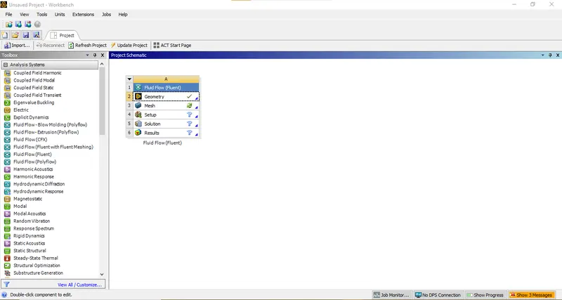
- Open ANSYS Workbench 2022R2 select Fluid Flow (Fluent) from Toolbox.
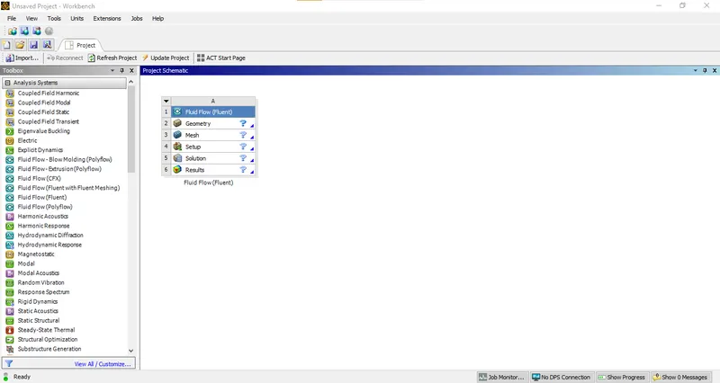
- Rename the file and left click Geometry and select New Spaceclaim Geometry.
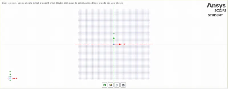
- Open the geometry STEP or SLDPRT of the geometry in spaceclaim.
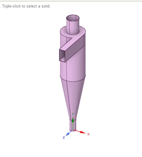
- Volume exact to cyclone seperator
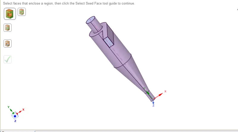
- Close SpaceClaim and double click on Mesh.
MESH
- Meshing window will appear.
- Mark Inlet, Outlet 1, Outlet 2 on geometry by right clicking each part and selecting Create Name Selection.
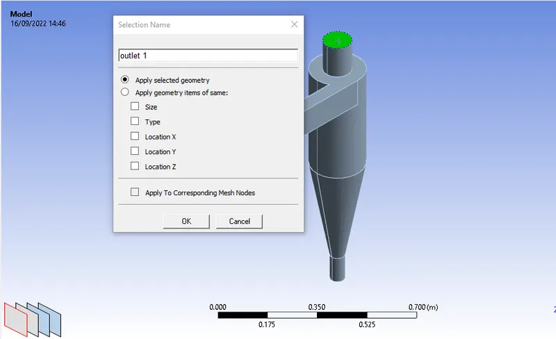
- Now select the mesh from the tree and generate mesh with an appropriate element size (10mm) to get a base-line meshing on the surface of geometry.
- The figure shown below show the geometry after meshing.
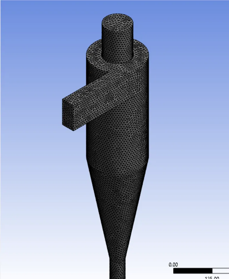
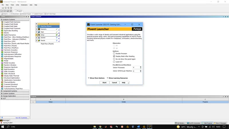
Close Meshing and double click on Setup, select Double Precision and Fluent window will open. Check all the values and make necessary correction if needed.
SETUP
Size Function: Proximity & Curvature
Min Element Size: 10mm
No of Nodes: 113728
No of Elements: 59175 Boundary
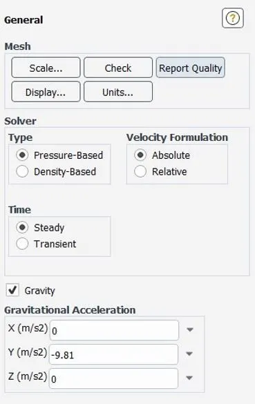
Gravity is enabled in the -ve y-direction.
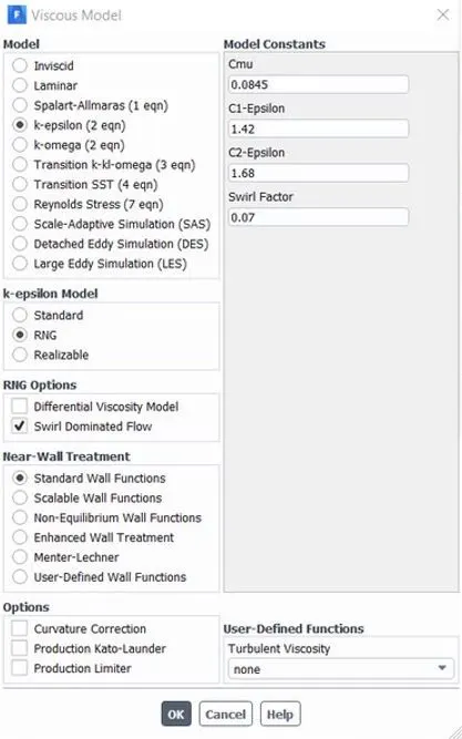
The swirl-dominated RNG K-epsilon model is used here to capture the flow more accurately.
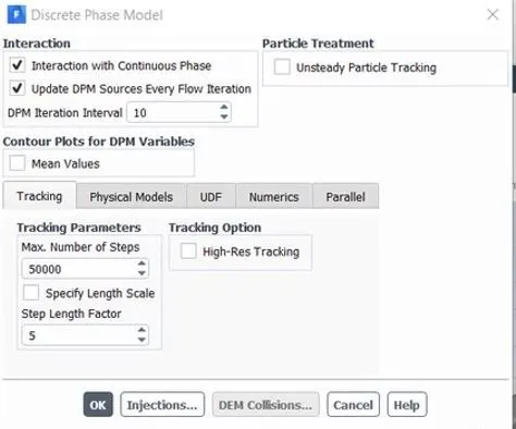
The Discrete phase modeling is used to track the flow of the particles.
No step for particle tracking = 50000
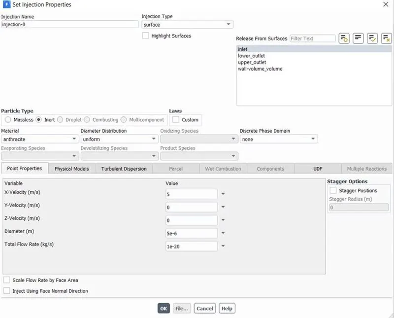
Injection Material: Anthracite (5microns in diameter)
Velocity Inlet: 3m/s
Outlet: Pressure Outlet( Gauge Pressure= 0Pa)
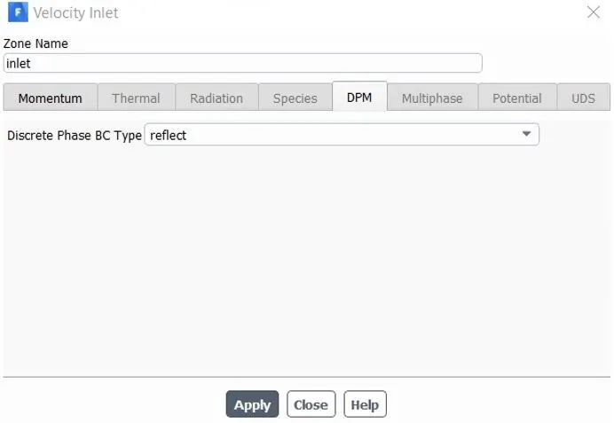
DPM Settings are varied b/w reflect, escape, trap & wall jet.
Reflect: The particle rebounds off the boundary in question with a change in its momentum as defined by the coefficient of restitution.
Escape: The particle escapes out when encountered by the boundary.
Trap: The trajectory calculation is terminated & fate of the particle is recorded as a trap.
Wall-Jet: The wall-jet type boundary condition is applicable for high-temperature walls where no significant liquid film is found & high Weber No impacts when the spray acts as a jet. This model is not applicable to regimes where the film is important.
SOLUTION APPROACH:
CASE 1
1) particle diameter = 1μm
Velocity = 3m/sec
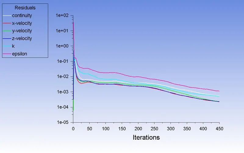
Residual:
Flow:
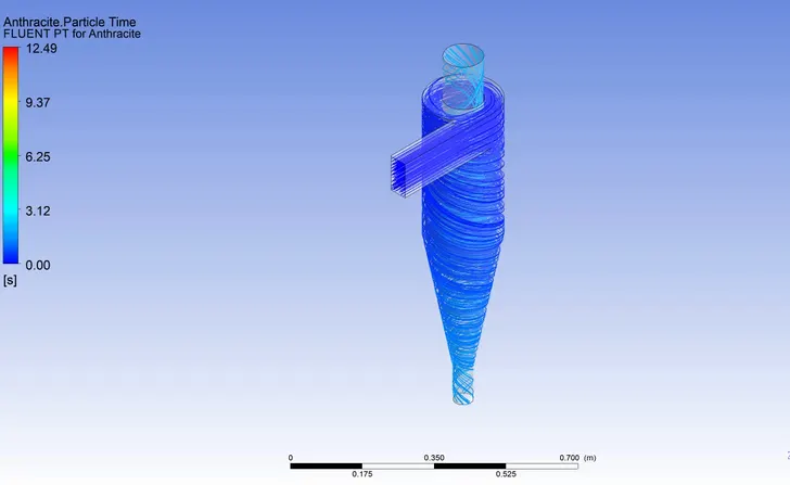
ANIMATION LINK
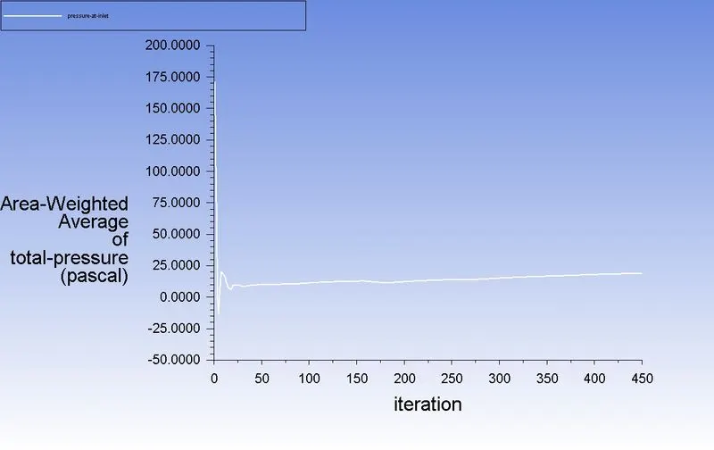
Pressure at inlet:
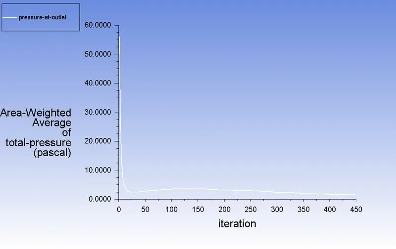
Pressure at outlet:
Pressure drop:
Pressure drop = Total inlet pressure - Total Outlet Pressure
= 171.86-54.49
Pressure drop = 117.37 pa
Efficiency:
Separation efficiency = (number of particles trapped/number of particles tracked )*100
number of particles tracked =124
number of particles trapped =29
So, separation efficiency = (29/124)*100 = 23.38%
2) particle diameter = 3μm
Velocity = 3m/sec
Residual:
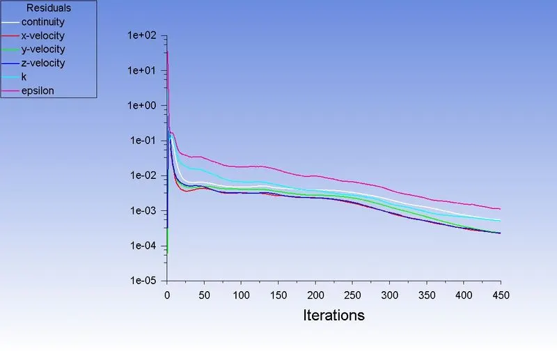
Flow:
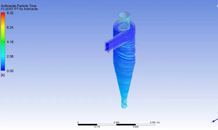
Animation:
Pressure at inlet:
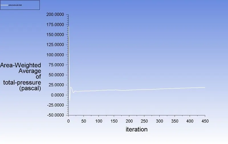
Pressure at outlet:
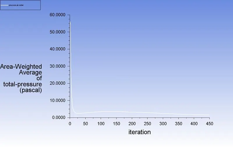
Pressure drop:
Pressure drop = Total inlet pressure - Total Outlet Pressure
= 171.86-54.49
Pressure drop = 117.37 pa
Efficiency:
Separation efficiency = (number of particles trapped/number of particles tracked )*100
number of particles tracked =124
number of particles trapped =98
So, separation efficiency = (98/124)*100 = 79.83%
3) particle diameter = 5μm
Velocity = 3m/sec
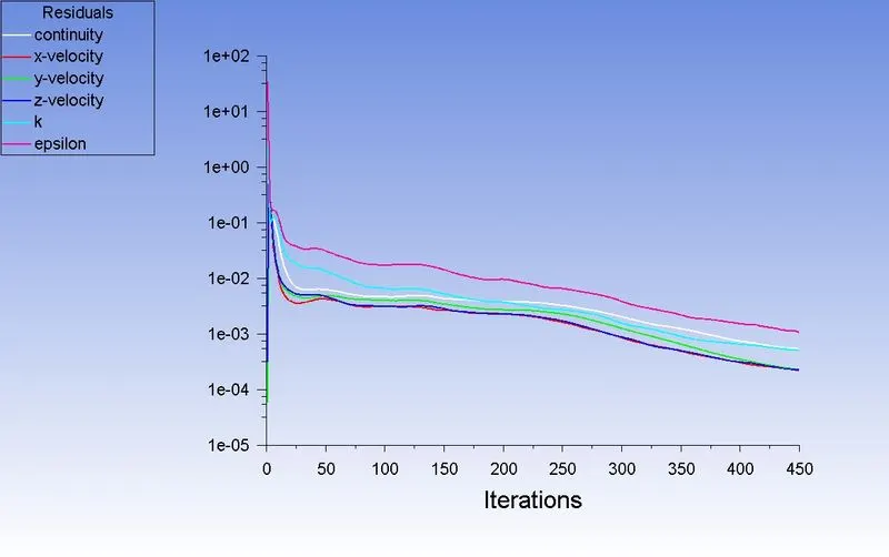
Residual:
Flow:
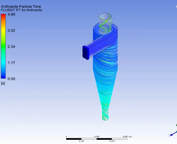
ANIMATION LINK
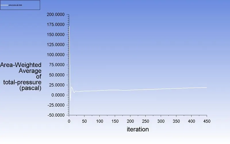
Pressure at inlet:
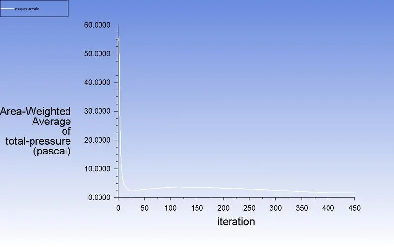
Pressure at outlet:
Pressure drop:
Pressure drop = Total inlet pressure - Total Outlet Pressure
= 171.86-54.49
Pressure drop = 117.37 pa
Efficiency:
Separation efficiency = (number of particles trapped/number of particles tracked )*100
number of particles tracked =124
number of particles trapped =115
So, separation efficiency = (115/124)*100 = 92.74%
| Diameter (μm) | Velocity (m/sec) | Particle Tracked | Particle Trapped | Separator Efficiency (%) | Pressure Drop(pa) |
| 1 | 3 | 124 | 29 | 23.38 | 117.37 |
| 3 | 3 | 124 | 98 | 79.83 | 117.37 |
| 5 | 3 | 124 | 115 | 92.74 | 117.37 |
CASE 2
1) particle diameter = 5μm
Velocity = 1m/sec
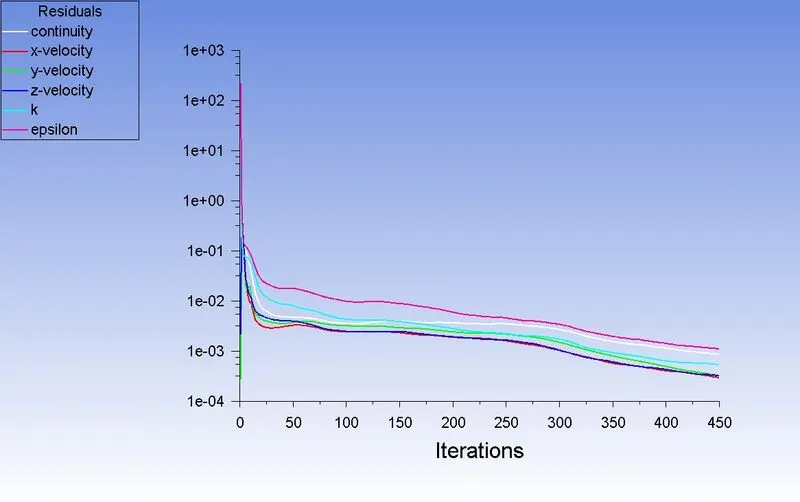
Residual:
Flow:
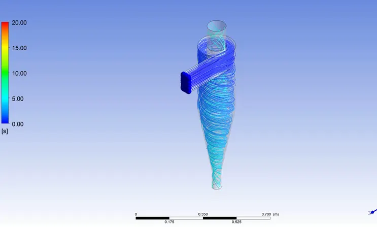
ANIMATION LINK
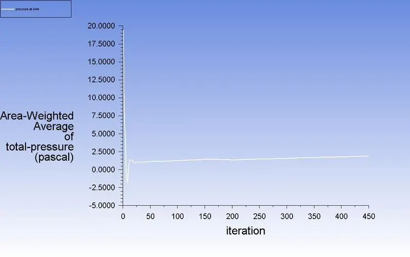
Pressure at inlet:
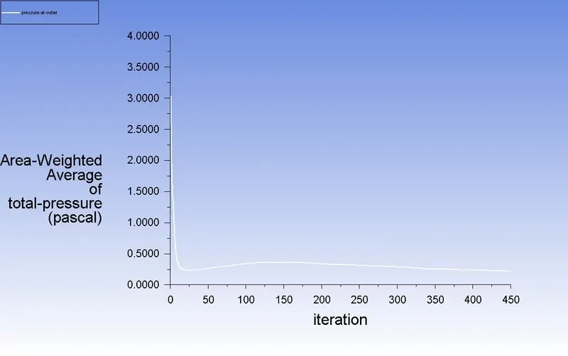
Pressure at outlet:
Pressure drop:
Pressure drop = Total inlet pressure - Total Outlet Pressure
= 19.47-3.03
Pressure drop = 16.44 pa
Efficiency:
Separation efficiency = (number of particles trapped/number of particles tracked )*100
number of particles tracked =124
number of particles trapped =9
So, separation efficiency = (9/124)*100 = 7.25%
2) particle diameter = 5μm
Velocity = 3m/sec
Residual:
Flow:
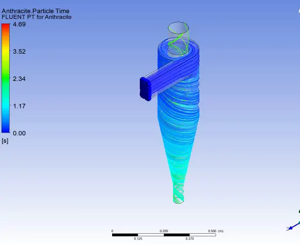
ANIMATION LINK
Pressure at inlet:
Pressure at outlet:
Pressure drop:
Pressure drop = Total inlet pressure - Total Outlet Pressure
= 171.86-54.49
Pressure drop = 117.37 pa
Efficiency:
Separation efficiency = (number of particles trapped/number of particles tracked )*100
number of particles tracked =124
number of particles trapped =115
So, separation efficiency = (115/124)*100 = 92.74%
3) particle diameter = 5μm
Velocity = 5m/sec
Residual:
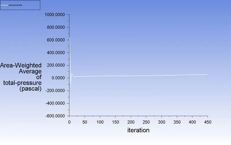
Flow:
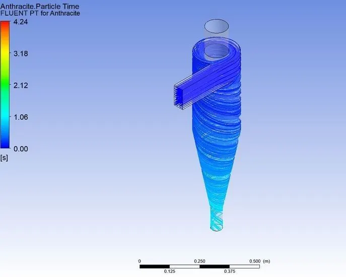
ANIMATION LINK
Pressure at inlet:
Pressure at outlet:
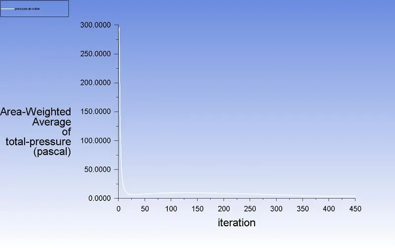
Pressure drop:
Pressure drop = Total inlet pressure - Total Outlet Pressure
= 645.65-289.99
Pressure drop = 355.66 pa
Efficiency:
Separation efficiency = (number of particles trapped/number of particles tracked )*100
number of particles tracked =124
number of particles trapped =123
So, separation efficiency = (123/124)*100 = 99.19%
| Diameter (μm) | Velocity (m) | Particle Tracked | Particle Trapped | Separator Efficiency (%) | Pressure Drop(pa) |
| 5 | 1 | 124 | 9 | 7.25 | 16.44 |
| 5 | 3 | 124 | 115 | 92.74 | 117.37 |
| 5 | 5 | 124 | 123 | 99.19 | 355.66 |
CONCLUSION:
- Simulation is done for particle size varying from 1 m to 5 m with air and particle velocity as 3m/s. From the video, it is observed that heavier particle is trapped at the bottom outlet and lighter particles are escaped at the outlet 1.
- But we can also see that lighter particles also get trapped at the bottom outlet because of interaction between lighter and heavier particles and there is an exchange of inertial forces between them as a result there is a transfer of Kinetic energy from heavier particle to the lighter particle, as a result,
- we can observe a certain number of heavier particles escapes through the top outlet.The collection efficiency of cyclones varies as a function of particle size, density, and cyclone design.
- Cyclone efficiency will generally increase with the increase in particle size, density, inlet duct velocity, cyclone body length, number of gas revolutions in the cyclone, the ratio of cyclone body diameter to gas exit diameter, inlet dust loading, smoothness of the cyclone inner wall.
- The efficiency of the cyclone will decrease with an increase in the parameters such as gas viscosity, cyclone body diameter, gas exit diameter, gas inlet duct area, gas density, leakage of air into dust outlet. With the increase in inlet velocity or particle size the efficiency increases..