Week 8 - Simulating Cyclone separator with Discrete Phase Modelling
Aim:- To perform analysis on cyclone separator and calculate the separation efficiency and pressure drop.
Objective:-
- To perform an analysis on a given cyclone separator model by varying the particle diameter from 1 μm to 5 μm and calculate the separation efficiency in each case. Discuss the results. [Use both the velocity's as 3m/sec.]
- To perform an analysis on a given cyclone separator model by varying the particle velocity from 1 m/sec to 5 m/sec and calculate the separation efficiency and pressure drop in each case. Discuss the results. [Use particle diameter size as 5 μm for all cases & keep flow velocity same as particle velocity]
- Analysing effect of particle size and inlet Gas velocity on separation efficiency of device along with effect of inlet velocity on pressure drop using plot.
Theory:-
Cyclones are devices that employ a centrifugal force generated by a spinning gas stream to separate particles from the gas. Their simple design, low cost capital and maintenance-free operation make them ideal for use as precleaners for more expensive final control devices such as baghouses or electrostatic precipitators. Cyclones are particularly well suited for high temperature and pressure conditions because of their rugged design and flexible component materials. Cyclone collection efficiencies can reach 99% for particles bigger than 5 micrometer and can be operated at very high dust loading. Cyclones are used for removal of large particles for both air pollution control and process use. Application in extreme condition includes removal of coal dust in a power plant and use as a spray dryer.
Engineers are generally interested in two parameters in order to carry out an assessment of the design and performance of a cyclone. These parameters are the collection efficiency of particle and pressure drop through the cyclone. An accurate prediction of cyclone efficiency is very important because an inaccuracy in the efficiency prediction may result in an inefficient design of the cyclone separator. CFD has a great potential to predict the flow field characteristics and particle trajectories inside the cyclone as well as the pressure drop. The complicated swirling turbulent flow in a cyclone places great demands on the numerical techniques and the turbulence models employed in the CFD codes when modelling the cyclone pressure drop.
This study presents an application of computational fluid dynamics, in the prediction of cyclone efficiency. This study also reviews the prediction of four different empirical models for cyclone efficiency, namely Lapple [1], Koch and Licht [2], Li and Wang [3], and Iozia and Leith [4] . The simulation results are then compared with experimental data found in the literature for different inlet flow rates, pressures and temperatures. In this study, the CFD calculations are carried out using a commercial finite volume code, FLUENT 6.0, and the empirical models are performed in Microsoft Excel spreadsheet.
Four empirical models used to calculate the cyclone separator efficiency:-
1. Lapple :-
Lapple [1] model was developed based on force balance without considering the flow resistance. Lapple assumed that a particle entering the cyclone is evenly distributed across the inlet opening. The particle that travels from inlet half width to the wall in the cyclone is collected with 50% efficiency. The semi empirical relationship developed by Lapple [1] to calculate a 50% cut diameter, `d_(pc)`, is
`d_(pc)=[(9mub)/(2piN_evi(rho_p-rho_g))]^(1/2)`
Where `N_e` is the number of revolutions
`N_e=1/alpha[h+(H-h)/2]`
The efficiency of collection of any size of particles is given by
`eta_i=1/(1+(d_(pc)/(bard_pi))^2`
2. Koch and Licht :-
Koch and Licht collection theory recognized the inherently turbulent nature of cyclones and the distribution of gas residence times within the cyclone. Koch and Licht described particle motion in the entry and collection regions with the additional following assumptions:
- The tangential velocity of a particle is equal to the tangential velocity of the gas flow, i.e. there is no slip in the tangential direction between the particle and the gas.
- The tangential velocity is related to the radius of cyclone by: `uR^n=`constant.
A force balance and an equation on the particles collection yields the grade efficiency `eta_i`
`eta_i=1-exp{-2[G_(tauiQ)/D^3(n+1)]^(0.5/(n+1))}`
where
`G=(8k_c)/(k_a^2K_b^2`
`n=1-{1-(12D)^0.14/2.5}{(T+460)/530}^0.3`
`tau_i=(rho_pd_pi^2)/(18mu)`
G is a factor related to the configuration of the cyclone, n is related to the vortex and `tau` is the relaxation term.
3. Li and wang model :-
The Li and Wang model includes particle bounce or reentrainment and turbulent diffusion at the cyclone wall. A two dimensional analytical expression of particle distribution in the cyclone is obtained. Li and Wang model was developed based on the following assumptions:
- The radial particle velocity and the radial concentration profile are not constant for uncollected particles within the cyclone.
- Boundary conditions with the consideration of turbulent diffusion coefficient and particle bounce reentrainment on the cyclone wall are:
C=`C_0`, at `theta`=0
`D_r(delc)/(delr)=(1-alpha)omegac`, at r=D/2
- The tangential velocity is related to the radius of cyclone by: `muR`=constant.
The concentration distribution in a cyclone is given as:
`c(r,theta)=(c_0(r_omega-r_n)exp{-lamda[1/(k(1+n))r^(1+n)]})/(int_(r_n)^(r_omega)exp{[1/(k(1+n))r^(1+n)}dr`
C=`C_0`, at `theta`=0
`D_r(delc)/(delr)=(1-alpha)omegac`, at r=D/2
- The tangential velocity is related to the radius of cyclone by: `muR`=constant.
The concentration distribution in a cyclone is given as:
`c(r,theta)=(c_0(r_omega-r_n)exp{-lamda[1/(k(1+n))r^(1+n)]})/(int_(r_n)^(r_omega)exp{[1/(k(1+n))r^(1+n)}dr`
where
`K=((1-n)(rho_p-rho_g)d^2Q)/(18mub(r_omega^(1-n)-r_n^(1-n))`
and
`lamda=((1-alpha)Komega_omega)/(D_rr_omega^n)`
The resultant expression of the collection efficiency for particle of any size is given as
`eta_i=1-exp{-lamdatheta_1}`
where
`theta_1=(2pi(S+L))/alpha`
4. Iozia and Leith Model :-
Iozia and Leith logistic model is a modified version of Barth Model, which is developed based on force balance. The model assumes that a particle carried by the vortex endures the influence of two forces: a centrifugal force, Z and a flow resistance, W. The collection efficiency `eta_i` of particle diameter `d_(p_i)` can be calculated from
`eta_i=1/(1+(d_(pc)/d_(p_i))^beta`
`beta` is an expression for slope parameter derived based on the statistical analysis of experimental data of a cyclone with D=0.25 m given as
`beta=0.62-0.87ln(d_(pc)/100)+5.21ln((ab)/D^2)+1.05[ln((ab)/D^2)]^2`
and `d_(pc)` is the 50 % cut size.
CAD setup and Modelling :-
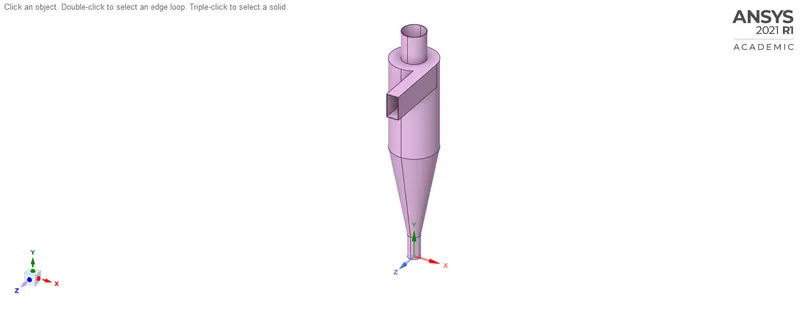
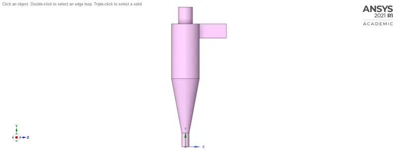
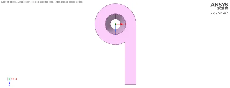
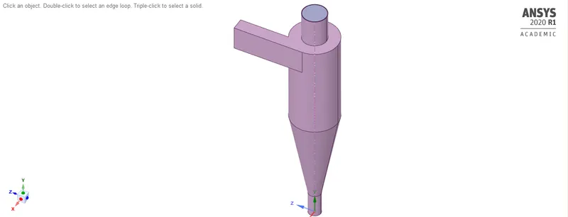
Here, We imported geometry into space-claim for CAD cleanup where solid part is removed and volume region is taken out from the model.
This Volume region is then saved and move forward for meshing into design modeler.
Importing Solid Geometry into Space-claim.
Different views of CAD Model(Solid part)
Isometric View :-
Side view :-
Top View :-
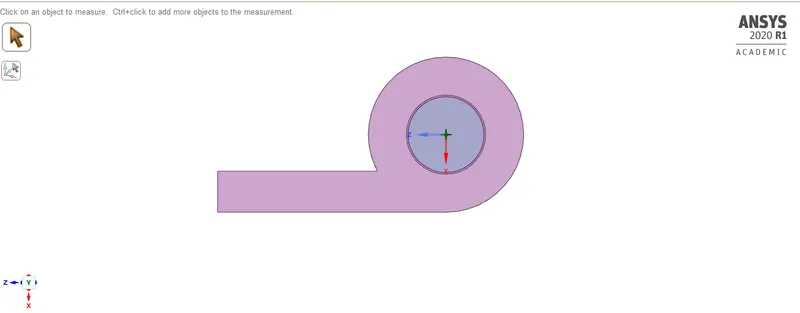
Different views of CAD Model(Volume region).
Isometric View :-
Side View :-
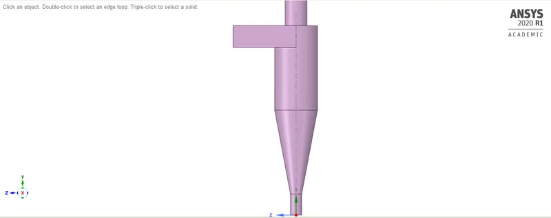
Top view :-
Meshing :-
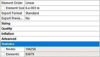
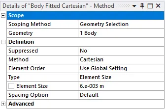
Here, We will discretize the volume region into smaller piece of chunks or We can say smaller elements known as Meshing. Here, We have use Base Mesh with Cartesian Method(Mesh Method) for discretisation of geometry in order ot reduce cell count which may cost in low computation time.
Mesh Details :-
Mesh Formation on Geometry :-
Trimetric View :-
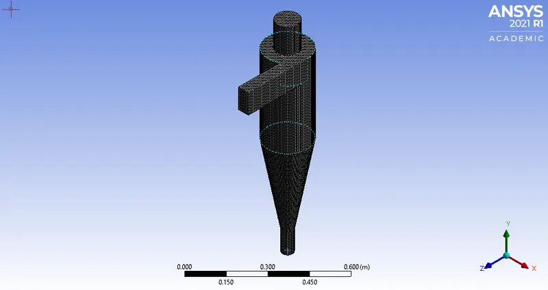
Side View :-
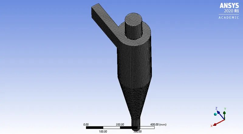
Setting up Simulation parameters, governing conditions and physical models in Fluent :-
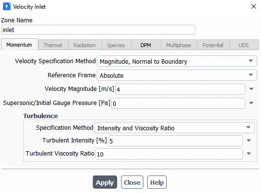
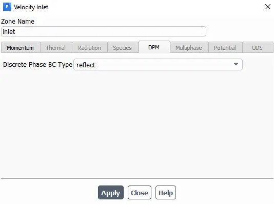
1. Boundary Conditions :-
Inlet
Top Outlet
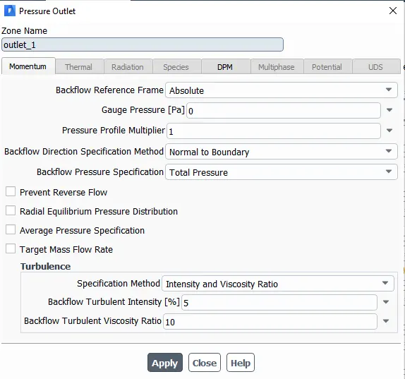
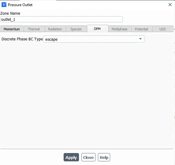
Bottom Outlet
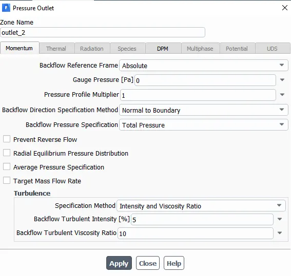
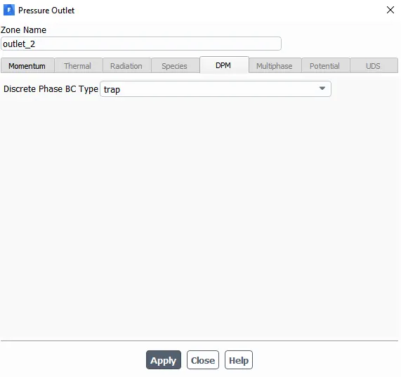
2. General setting for governing equations :-
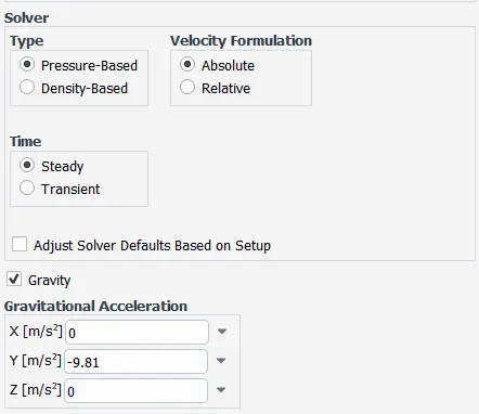
Here, We have use Pressure based solver for solving governing equations since We are considering velocity of particle is very low in cyclone separator. Along with it, We use steady based simulation condtion in order to achieve results quickly.
3. Turbulence Modelling :-
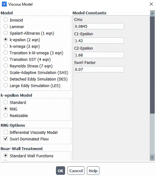
Since fluid coming into the chamber have vortex flow, It will have turbulence. So, Keeping in mind this We have provided here K-epsilon with RNG which is well suited for vortex flow. Along with it, We have use swirl dominated flow with standard wall functions in order to capture swirling in the flow along downward direction and phyiscs going around wall when partilces impeach on the wall.
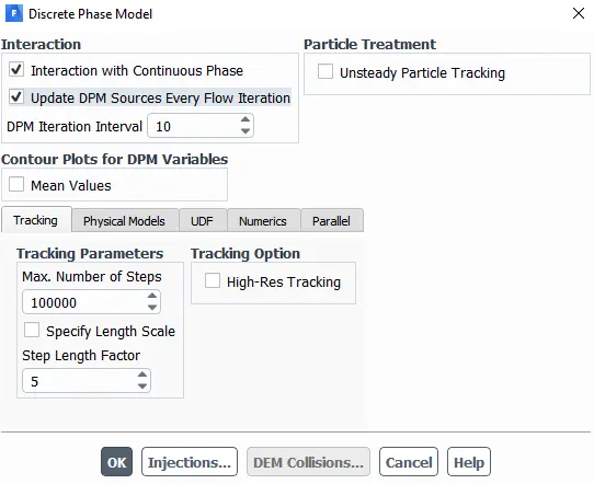
4. Discrete Phase Modelling :-
General setting :-
Injection Parameters:-
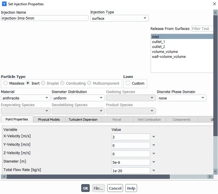
We have assume particle size to be 5 micrometer which is being inject into chamber from inlet surface. Here, Particle size and velocity used as demonstration purpose to show how settings is set. However, Both properties have been altered according to cases.
Here, particle used is anthracite(a type of coal) whose shape is considered uniform.
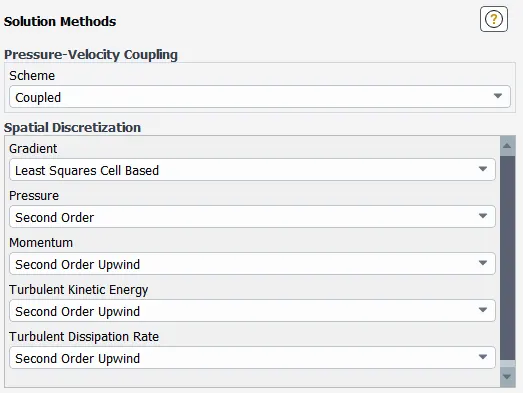
5. Solution Methods :-
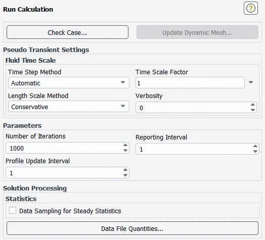
6. Simulation Run Parameters :-
Results :-
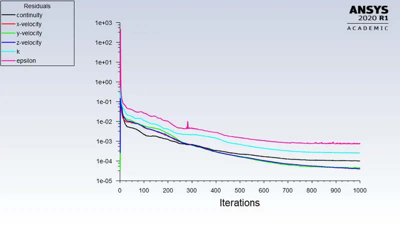
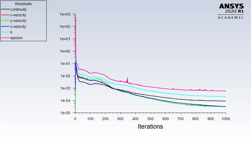
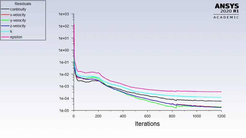
Residuals plot on the basis of velocity:-
At 5 m/s
At 3 m/s
At 1 m/s
Residuals plot on the basis of Particle size:-
For 5 micrometer :-
For 2.5 micrometer :-
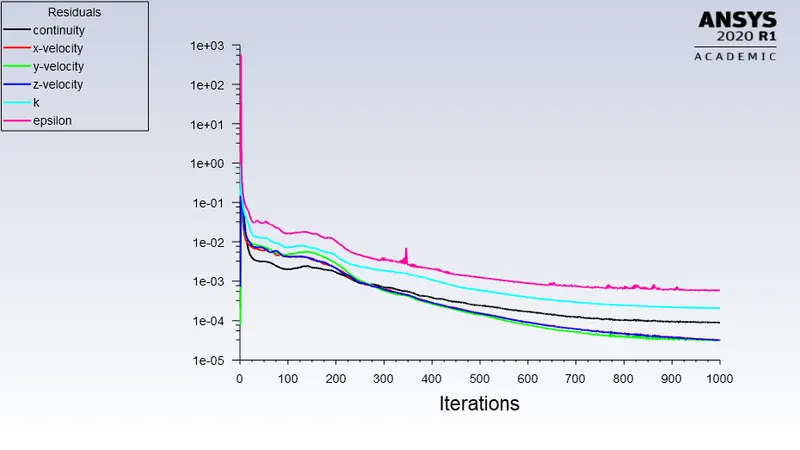
For 1 micrometer :-
Animation on the basis of different velocity of particles :
At 5 m/s
At 3 m/s
At 1 m/s
Animation on the basis of different size of particles :
For 5 micrometer
For 3 micrometer
For 1 micrometer
Observation made from the simulation and following analysis were made using plot:-
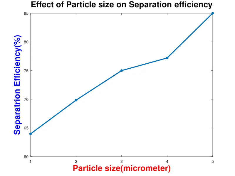
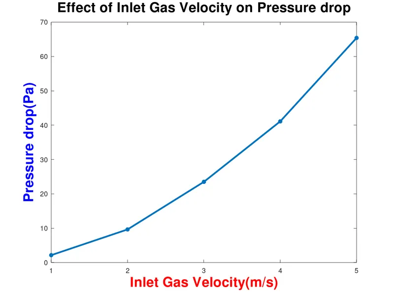
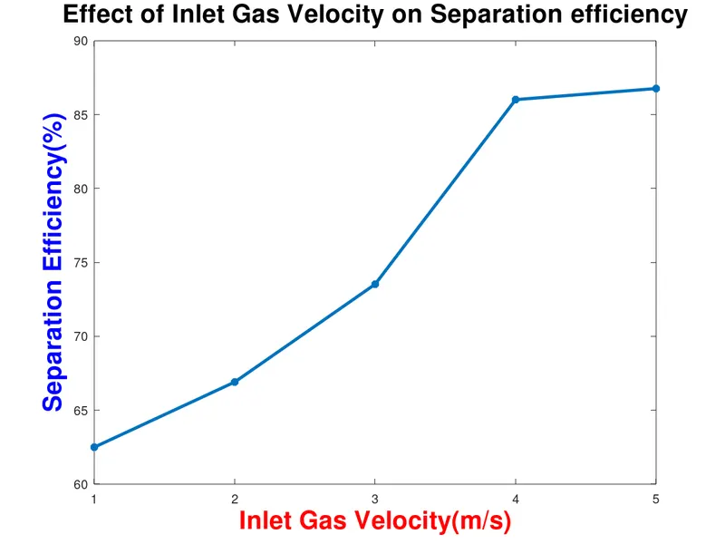
Here We obtain the result using simulation in Fluent for pressure drop(for velocity only) and separation efficiency on the basis of velocity and particle size. Then, We noted down the value obtain for each case separately then generated different plot using MATLAB software.
So following information We get from the plot :-
1) Pressure drop across device(cyclone separator) decreases on increase in inlet gas velocity in device.
2) Separation efficiency increases on increasing the inlet velocity for particular particle size.
3) Separation efficiency decreases on decreasing the particular particle size for particular inlet velocity .
Conclusion :-
1) Here We concluded that if We have to achieve high separation efficiency then We have to keep inlet velocity high for device but for that, pressure drop will be high that mean We need some extra workdone which will replicate in the form of power consumption.
2) For particle size, Separation efficiency have higher rate for bigger particle size that mean if We have to maintain good success ratio then We need a decent particle size, here which was 5 micrometer otherwise performance will bad for smaller particle size.