Week_8_Plastic Model_1
AIM: To perform midsurfacing and meshing of the given plastic model and assign the various thickness.
Element quality criteria:
| S.N | Quality criteria | Value |
| 1. | Target element length | 5mm |
| 2. | Aspect ratio | 3 |
| 3. | Skewness | 45 |
| 4. | Warping | 30 |
| 5. | Taper | 0.5 |
| 6. | Min. Length | 3mm |
| 7. | Max. Length | 7mm |
| 8. | Min angle quad | 45 |
| 9. | Max angle quad | 135 |
| 10. | Min angle tria | 30 |
| 11. | Max angle tria | 110 |
| 12. | Tria% | 15 |
PROCEDURE:
- The plastic model is first imported into hypermesh.
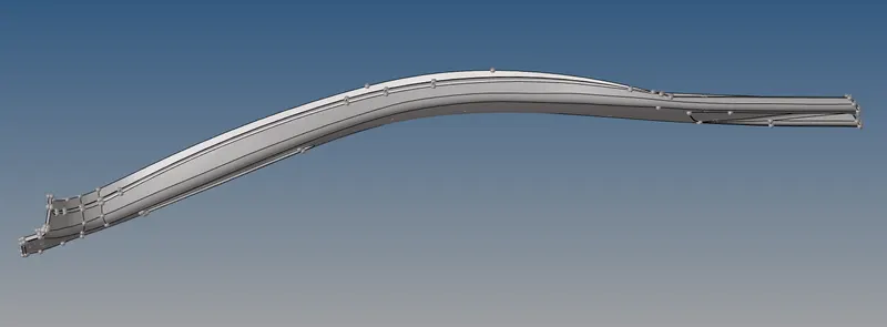
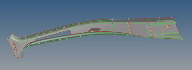
- The midsurface is obtained by using the midsurface option.
- Now the midsurface is inspected and corrected of any imperfections, like shown below.
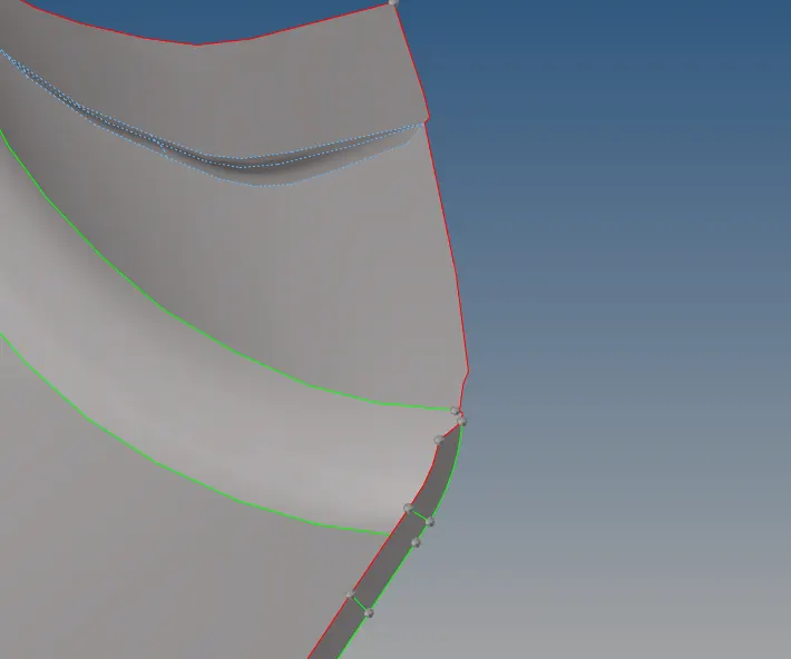
- Geometry is corrected by using options like extend, trim with surface in the surface edit and quick edit options. A part which needs correction is shown below,
- The component is divided into small segments to make the meshing easy, by understanding the mesh flow the geometry is split and meshed along the flow, part after another.
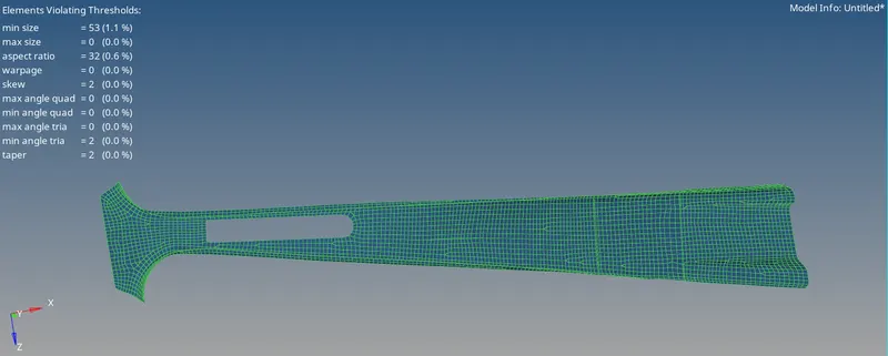
- The mesh is corrected by using quality index tools, edit element and element cleanup.
- Triangular elements are avoided along the free edges and trias are not made to face towards each other.
- Some elements do fail for minimum size along the edges, these can be avoided of correction as shown below,
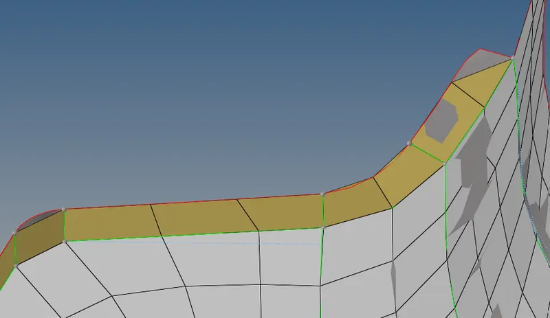
- Using the edges option we will provide the equivalence.
- Thickness can be applied by the usual manual method or the automatic method, for this model we used the automatic method.
- For automathic thickness we go to the Mesh<Assign<Midmesh thickness.
- For the surfaces we will enable only the parent component and select the entire component's surface by displayed option.
- For the elements we will enable only the mesh in the midsurface component and select by displayed option.
- For thickness output we will select properties on components and give calculate thickness.
- These will create and assign the thickness to the respective mesh of the surfaces and they will be represented by different colours accourdingly.
- However this automatic method will result in some elements being not appointed of the correct thickness as below,
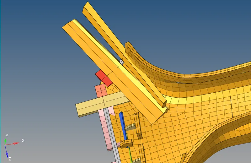
- To correct this error we will use the organise option to element the individualy and move them to their respective component according to the thickness and colour provided for easier understanding.
- The final mesh after the thickness being assigned to the elements is as shown below,
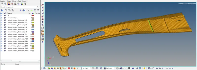
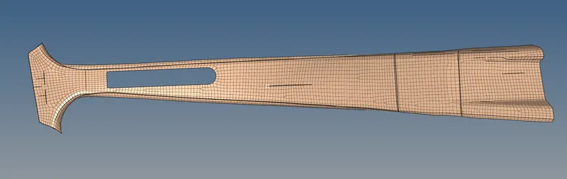
Fully meshed model:
RESULT:
A midsurface has been obtained and mesh has been generated for the plastic model. The thickness is also assigned to the model.