Week 8 Multi cell Battery Pack
Introduction to Battery Technology for Electric Vehicles using MATLAB & Simulink
Week 8 Multi cell Battery Pack
Q.How weakest cell limits the usable capacity of the battery pack? What is the solution?
Ans=>
Weakest cell limits the usable capacity of the battery pack. Any element which is imposing certain limitation of charging and discharging battery pack, it imposes a limit on overall operation, due to to weakest cell reaching the limit earlier than others, battery pack is going to be under utilised.
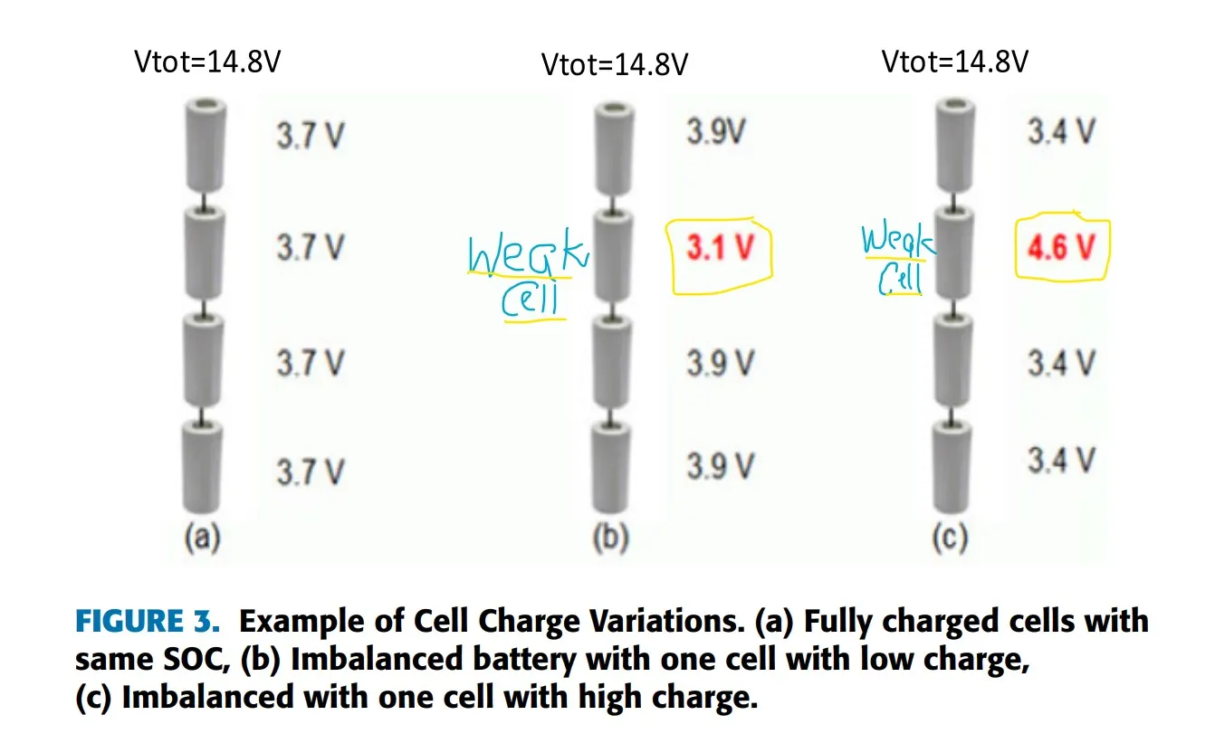
The cells in series above Fig 3 is showing a Weak /faulty cell in red with different voltage than normal cell voltages of rest. That's why Proper Cell Balancing is Necessary in Battery Packs.
When a lithium battery pack is designed using multiple cells in series, it is very important to design the electronic features to continually balance the cell voltages. This is not only for the performance of the battery pack, but also for optimal life cycles.
The use of cell balancing enables us to design a battery with larger capacity for an application because balancing allows the battery to achieve a higher state of charge (SOC). A lot of companies choose not to use cell balancing at the start of their design do reduce cost but without the investment in the cell balancing hardware and software, the design does not allow the SOC to approach 100 percent.
What is Cell Imbalance?
If lithium cells are overheated or overcharged, they are prone to accelerated cell degradation. They can catch fire or even explode as a thermal runaway condition can occur if a lithium ion cell voltage exceeds 4.2 V by even a few hundred millivolts.
Every pack that we design and manufacture at Epec has an overvoltage protection circuit (sometime even a backup) to go along with standard cell balancing that will prevent such an event from ever occurring. In a multi-cell battery pack, which is commonly used in laptop computers and medical equipment, placing cells in series opens up the possibility of cell imbalance, a slower but persistent degradation of the battery.
What is Need for Cell Balancing?
When you need several cells grouped together to power a device, you need to do some sought of balancing. The reason is that battery cells are fragile things that die or get damaged if they are charged or discharged too much. For your cells that have different SoC and you start using them, their voltage starts dropping until the cell with the least amount of energy stored in it reaches the discharge cut off voltage of the cell.
At that point, if the energy keeps owing through the cell, it gets damaged beyond repair. Now, if you attempt to charge this group of cells to the correct combined voltage, the healthy cells get overcharged and thus get damaged as they will take the energy that the already dead cell is no longer able to store. Imbalanced lithium-ion cells die the first time you try to use them. This is why balancing is absolutely required.
Other reasons for cell balancing include:
=Thermal Runaway
Battery cells, especially lithium cells are very sensitive to overcharging and over-discharging. This leads to thermal runaway when the rate of internal heat generation exceeds the rate at which the heat can be released. By the use of cell balancing, every non-defective cell in the battery pack should be balanced to the same relative capacity as the other non-defective cells. Other than using cell balancing, you can keep the pack cool since heat is one of the primary factors that lead to thermal runaway. This minimizes the retention of heat in the pack. You should maintain the battery environment at room temperature.
=Cell Degradation
When a lithium cell is overcharged even slightly above its recommended value the energy capacity, effciency, and life cycle of the cell reduces. Cell degradation is mainly caused by:
1. Mechanical degradation of electrodes or loss of stack pressure in pouch-type cells.
2. Growth of solid electrolyte interface (SEI) on the anode. SEI is seen as a cause for capacity loss in most, if not all, graphite-based Li-ion when keeping the charge voltage below 3.92v/cell.
3. Formation of electrolyte oxidation (EO) at the cathode that may lead to sudden capacity loss.
4. Lithium-plating on the surface of the anode generated by high charging rates. Cell degradation is a serious economic problem that varies according to how the battery is being used.
=Incomplete Charging of a Cell Pack
Batteries are charged at a constant current of between 0.5 and 1.0 rate. The battery voltage rises as the charging progresses to peak when fully charged then subsequently falls. Consider three cells with 77 Ah, 77 Ah, and 76 Ah respectively and 100 percent SoC and all cells are then discharged and their SoC goes down. You can gure out quickly that cell 3 becomes rst to run out of energy since it has the lowest capacity.
When power is put on the cell packs and the same current is owing through the cells, once again, cell 3 lags behind during charging and may be considered fully charged as the other two cells are fully charged. This means that cells 3 have a low Coulometric Effciency (CE) due to the cell’s self-heating that results in cell imbalance.
=Incomplete Use of Cell Pack Energy
Drawing more current than the battery was designed for or short-circuiting the battery is most likely to cause premature failure of the battery. When discharging the battery pack, the weaker cells discharge faster than the healthy cells whereas they reach the lowest voltage more quickly than other cells. Providing regular rest periods during operation of the battery allows the chemical transformations in the battery to keep track of the demand for current.
Here is typical example of weak faulty cell in battery pack & its simulation in MATLAB:
Lithium-Ion Battery Pack With Fault
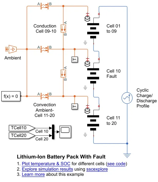
This example shows how to simulate a battery pack consisting of multiple series-connected cells in an efficient manner. It also shows how a fault can be introduced into one of the cells to see the impact on battery performance and cell temperatures. For efficiency, identical series-connected cells are not just simply modeled by connecting cell models in series. Instead a single cell is used, and the terminal voltage scaled up by the number of cells. The fault is represented by changing the parameters for the Cell 10 Fault subsystem, reducing both capacity and open-circuit voltage, and increasing the resistance values.
Model
Results
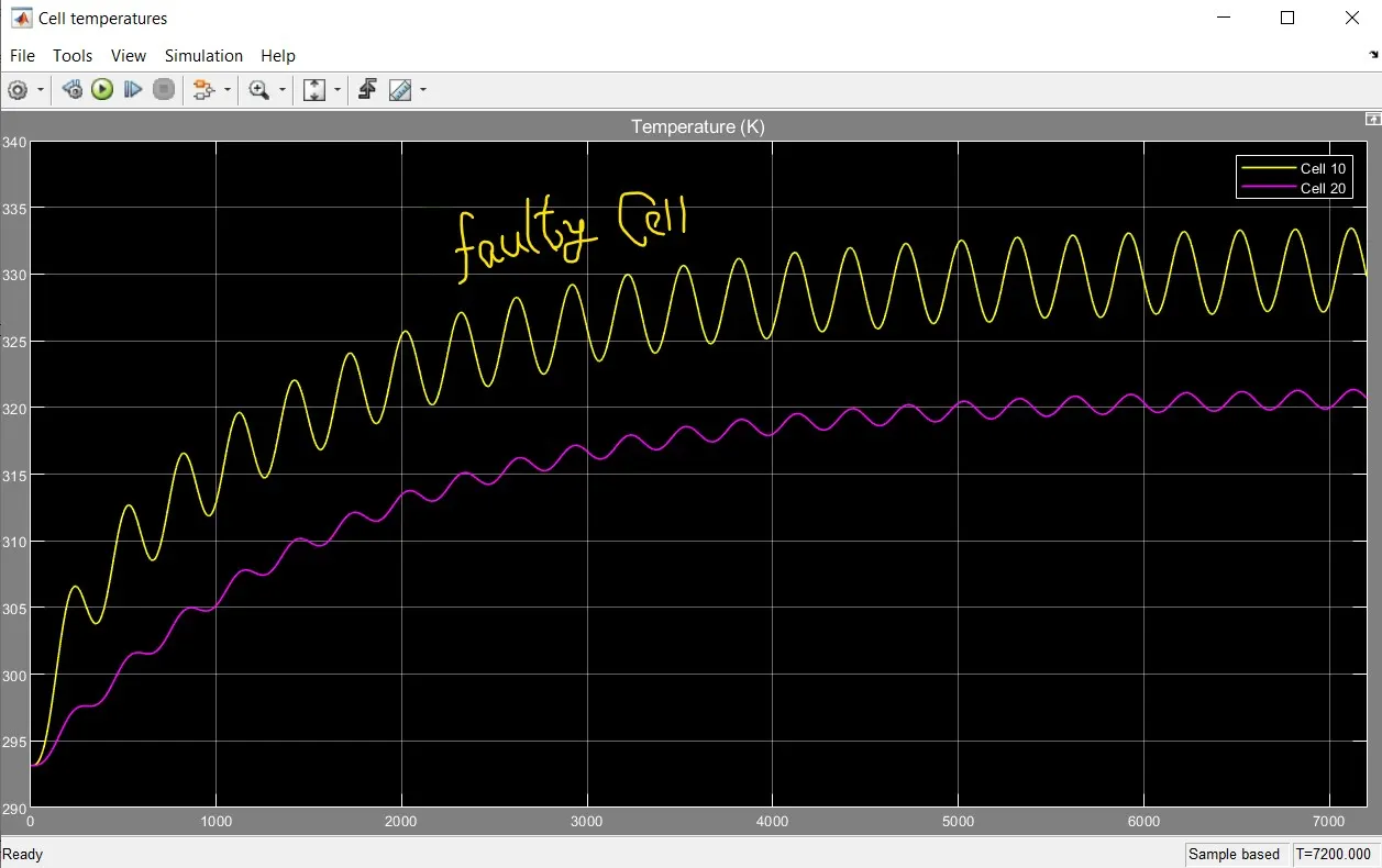
The scope above is showing simulation result of 20 cells, the yellow graph is of a fault cell undergoing high temperature causing to overheat, compared to the rest which are at nominal battery temperature.
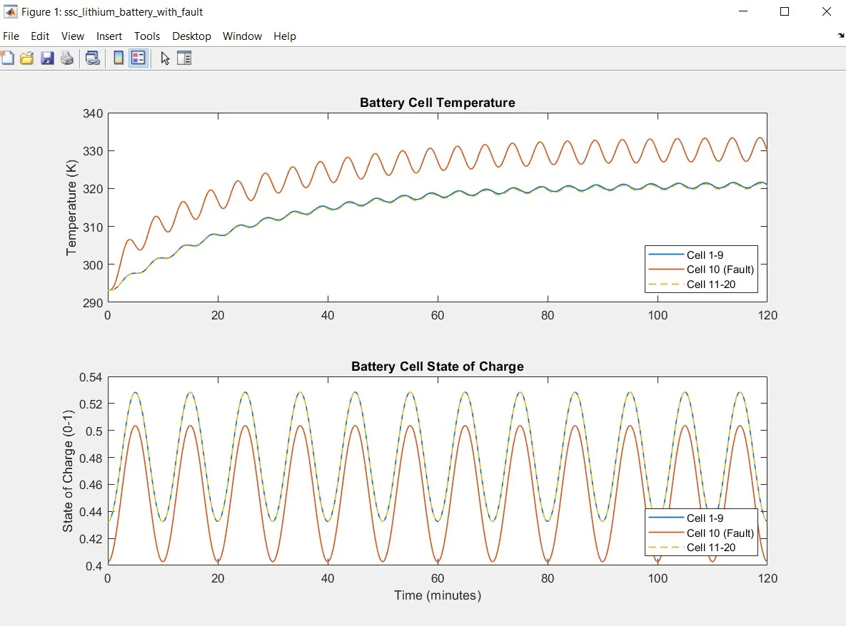
The red graph on SOC above is showing cell 10 fault at 0.5 and the other 19 cells are at the required battery state of charge of .52.
=> Solutions
What is Cell Balancing?
Cell balancing is the process of equalizing the voltages and state of charge among the cells when they are at a full charge. No two cells are identical. There are always slight differences in the state of charge, self-discharge rate, capacity, impedance, and temperature characteristics. This is true even if the cells are the same model, same manufacturer, and same production lot. Manufacturers will sort cells by similar voltage to match as close as possible, but there are still slight variations in the individual cells impedance, capacity, and self-discharge rate that can eventually lead to a divergence in voltage over time.
Most typical battery chargers detect full charge by checking whether the voltage of the entire string of cells has reached the voltage regulation point. Individual cell voltages can vary as long as they don’t exceed the limits for overvoltage protection. However, weak cells (ones with lower capacity / higher internal impedance) tend to exhibit higher voltage than the rest of the series cells at full charge termination. These cells are then weakened further by continuous overcharge cycles. The higher voltage of the weaker cells at charge completion causes accelerated capacity degradation. If the maximal recommended charging voltage is exceeded even by as little as 10 percent, it will cause the degradation rate to increase by 30 percent.
On the discharge side, the weak cells tend to have lower voltage than the other cells, due to either higher internal resistance, or a faster rate of discharge that results from the lower capacity. This means that if any of the weak cells hits the cell under voltage protection limit while the pack voltage is still sufficient to power the system, the full capacity of the battery will never be used as the pack protector will prevent over discharge (which would damage the cell) by stopping the discharge of the whole pack when one cell voltage goes below the cell under voltage threshold (usually around 2.7 V).
Cell Balancing Techniques
The fundamental solution of cell balancing equalizes the voltage and state of charge among the cells when they are at a fully charged state. Cell balancing is typically categorized in two types:
1. Passive
2. Active
Passive Cell Balancing
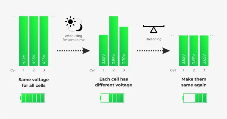
The passive cell balancing method is somewhat simple and straight forward. Discharge the cells through a dissipative bypass route. This bypass can be either integrated or external to the integrated circuit (IC). Such an approach is favorable in low-cost system application. The fact that 100% of the excess energy from a higher energy cell is dissipated as heat makes the passive method less preferable to use during discharge because of the obvious impact on battery run time.
A passive system potentially burns off excess energy from the high cells through a resistive element until the charge matches the lower energy cells in the pack. If you have cells packed in series and you notice that some of the cells have higher energy than the other lower energy cells, you can balance the cells in burning energy of the top cells simply by attaching a resistor to the cells which releases the energy into heat thereby equalizing the cell energy of the battery pack.
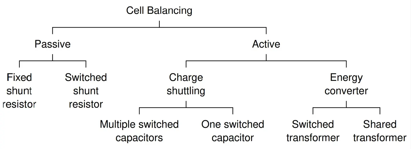
Initially, you burn off the excess energy until you have balanced cells. Passive cell balancing allows all cells to appear to have the same capacity. There are two different categories of passive cell balancing method: fixed shunting resistor and switching shunting resistor. A Fixed shunting resistor circuit is usually connected to the fixed shunting to prevent it from being overcharged. With the help of the resistors, the passive balancing circuit can control the limit value of each cell voltage without damaging the cells. Energy consumed by these resistors for balancing a battery may result in thermal losses in the BMS. This, therefore, proves the fixed shunting resistor method to be an inefcient cell equalizing circuit. The switch shunting resistor cell balancing circuit is currently the most common method in cell equalizing. This method has a continuous mode and a sensing mode, where the continuous mode all switches are controlled to be turned on or off at the same time and in the sensing mode, a real-time voltage sensor is required for each cell. This cell balancing circuit consumes high energy through a balancing resistor. This cell balancing circuit is suitable for a battery system that requires a low current when it is charged or discharged.
Active Cell Balancing
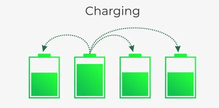
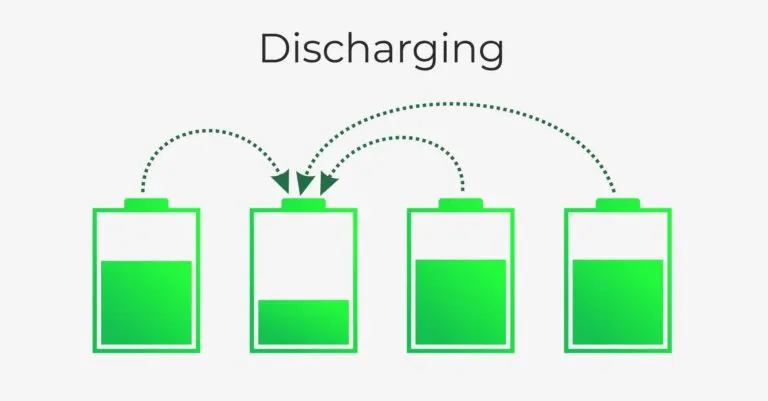
Active cell balancing, which utilizes capacitive or inductive charge shuttling to transfer charge between battery cells, is significantly more efficient because energy is transferred to where it is needed instead of being bled off. Of course the trade-off for this improved efficiency is the need for additional components at higher cost.
An active cell balancer generally transfers energy from one cell to another. That is from high voltage/ high SoC to a cell with a lower SoC. The purpose of an active balancer is that if you have a pack of cells with lower capacity, you can extend the life or the SoC that you have on the pack by moving energy from one cell in the pack with more energy than the other cell.
Instead of wasting all that energy as heat, an active cell balancer effciently balances cells with tiny converter circuits that pass energy from the highest voltage cells to the lowest voltage cells. There are two different categories of active cell balancing methods: charge shuttling and energy converters. Charge shuttling is used to actively transport charges from one cell to another to achieve equal cell voltage. Energy converters use transformers and inductors to move energy among the cells of a battery pack.
Circuit topologies for balancing
The most common topologies are
Ex.
Passive: Switched shunt resistor
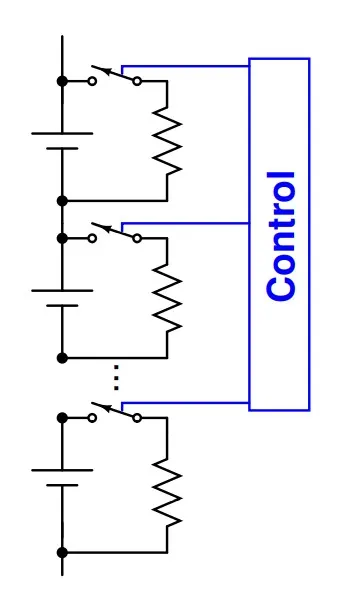
-A variation that works for Li-ion is to replace zener diode with BMS-controlled switch (some kind of transistor circuit)
-Electronics required to control transistor make this design more complicated; however, allows for much greater flexibility in balancing strategy
-BMS closes switches on cells having too much charge, allowing them to drain
-Added complexity is not as big an issue as it used to be Modern battery-stack monitoring chips have built-in circuitry to control either internal transistor (for slow balancing) or an external transistor (for faster balancing).
Active: Multiple switched capacitors
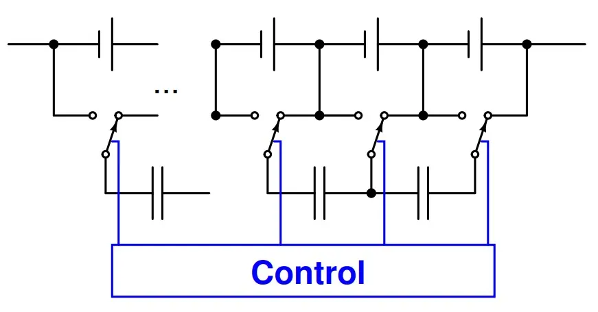
-In circuit, there is one fewer capacitor than there are battery-pack cells
-Single-pole-double-throw (transistor circuit) switches repeatedly back and forth (no intelligence)
-Consider two neighboring cells:
-High-voltage cell charges capacitor to its voltage, then low-voltage cell discharges capacitor to its voltage: charge moves to equalize cell voltages
-Over the course of time, entire pack is equalized. But, charge takes a long time to propagate from one end of the pack to the other.
Summary
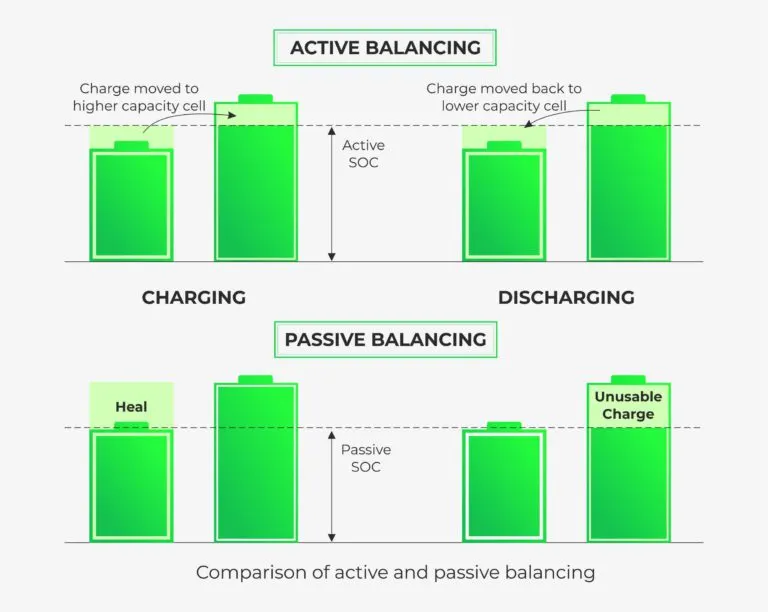
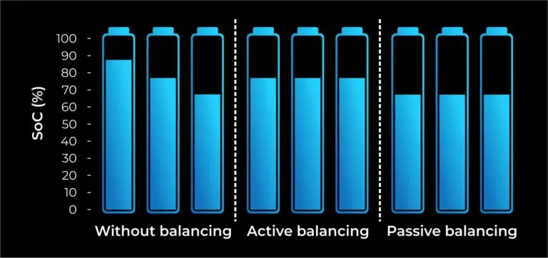
Cell balancing is not only important for improving the performance and life cycles of the battery, it adds an element of safety to the battery. One of the emerging technologies for enhancing battery safety and extending battery life is advanced cell balancing. Since new cell balancing technologies track the amount of balancing needed by individual cells, the usable life of battery packs is increased, and overall battery safety is enhanced.
Reference:
(https://www.batterypoweronline.com/)