Week 8 Multi cell Battery Pack
The individual cells in a battery pack naturally have somewhat different capacities, and so, over the course of charge and discharge cycles, may be at a different state of charge (SOC). Variations in capacity are due to manufacturing variances, assembly variances (e.g., cells from one production run mixed with others), cell aging, impurities, or environmental exposure.
Balancing a multi-cell pack helps to maximize capacity and service life of the pack by working to maintain equivalent state-of-charge of every cell, to the degree possible given their different capacities, over the widest possible range. Balancing is only necessary for packs that contain more than one cell in series. Parallel cells will naturally balance since they are directly connected to each other, but groups of parallel wired cells, wired in series ( parallel-series wiring ) must be balanced between cell groups.
To prevent undesirable, and often unsafe conditions, the battery management system must monitor the condition of individual cells for operational characteristics such as temperature, voltage, and sometimes current drawn – although the latter is often only measured per-pack rather than per-cell, perhaps with one-shot protection at the cell level against abnormally high current (such as in a short, or other failure condition.)
Under normal operation, discharging must stop when any cell first runs out of charge even though other cells may still hold significant charge. Likewise, charging must stop when any cell reaches its maximum safe charging voltage. Failure to do either may cause permanent damage to the cells, or in extreme cases, may drive cells into reverse polarity, cause internal gassing, thermal runaway, or other catastrophic failures. If the cells are not balanced, such that the high and low cutoff are at least aligned with the state of the lowest capacity cell, the energy that can be taken from and returned to the battery will be limited.
There are two major approaches to balancing: Passive balancing, and active balancing.
- In order to meet cost targets for hybrid electric(HEV), plug-in hybrid electric (PHEV), and all-electric vehicles(EV), an improvement in the battery life cycle and safety is essential.
- Despite research initiatives, lithium-based batteries have not yet been able to meet steep energy demands, long lifetime, and low cost of vehicular propulsion applications.
- One practical approach to improve performance is to use power electronics intensive cell voltage equalizers, in conjunction with on-board energy storage devices.
- Battery of a plug-in hybrid electric vehicle (PHEV) consists of a long string of cells (typically 100 cells, about 360 V),
- Where each cell is not exactly equal to the others, in terms of the capacity and internal resistance, because of the normal dispersion during manufacturing.
- In fact, a smarter solution lies in a power electronic battery cell voltage equalizer, which can improve not only the cycle life of batteries, but also their calendar life, power, and safety.
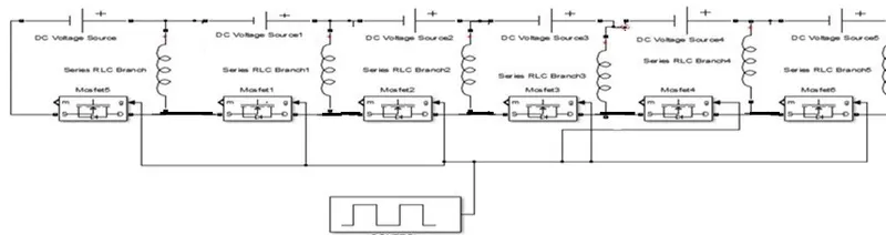
- The objective of this project is to introduce a simplified control scheme, based on open-circuit voltage estimation, for a novel cell equalizer configuration, with the potential to fulfil expectations of the following: 1) low cost; 2) large currents; and 3) high efficiency.
- This cell equalizer has the ability to drive high current with high efficiency.
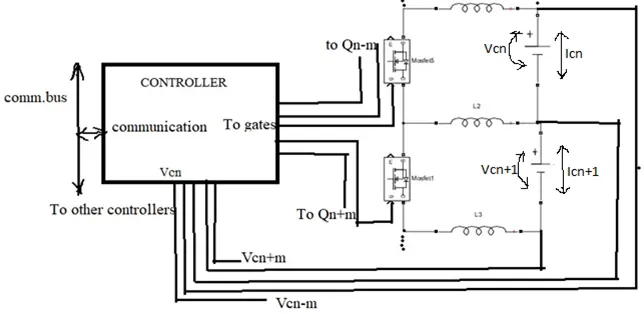
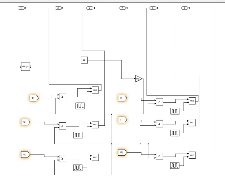
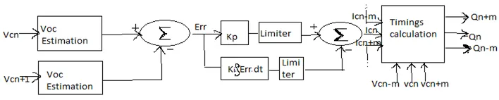
- The control block calculates the timing of the MOSFETs based on the voltage of the cells and the desired current.
- The current is calculated to reduce the equalization time, taking into account the following: 1) the voltage limit of each cell; 2) the total equalizer current limit; and 3) the equalizer timing limits.
-
Voc Estimation Algorithm
- It is possible to calculate the voltage on a battery cell (Vt), during a forced step change of current, such as the one generated when the equalizer turns off, using the following equation.
- The Icn is the cell current, which is composed of the IBatt and the IEQn (equalizing current)
- The open-circuit voltage (VOC) has a nonlinear relationship with SOC, temperature and age, and represents the chemically stored energy.
- The internal resistance is also dependent on SOC, temperature and age. Hence, internal resistance is not a constant.
- The VOC estimator needs to interrupt the equalizing current for at least 4 s, in order to record the measurements of cell voltage.
- The VOC of each cell is estimated using cell voltage measurements, cell equalizing currents, provided by the equalizer hardware using the cell voltages and the load current,and finally, using the load current, taken from the system controller.
- The objective is to equalize the VOC of each cell, so that the difference is used as the error signal, as represented in Err = Vcn+1 − Vcn
- First is the system stability, for which the KP and KI factors should be small enough. Thereafter, the steady-state error is considered, which is corrected by the KI -factor.
- In addition, there exist issues, such as the following: 1) sampling time; 2) noise and
3) quantization.
- In this experiment, the coefficient KP had to be reduced from the initial stability estimation, because high levels of quantization noise of the output stage generated too much noise in VOC estimation.
- This noise, in turn, was amplified by a high KP factor, resulting in a bad signal-to-noise result in the output.
- Thus, the system needed to be overdamped, due to the noise.
- In order to prove the performance of the equalizer to a full extent, a string of five cells were used, where all cells were half-charged, except one (cell #2), which was almost discharged.
- For testing purposes, the total battery voltage was kept constant.
- This was achieved by using an external power supply, to provide a small current proportional to the equalizer losses.
- The equalizer should provide current to cell #2 (positive current), while absorbing current (energy) from the rest of the cells (negative current), in an almost equal fashion.
- In order to prove the performance of the equalizer to a full extent, a string of five cells were used, where all cells were half-charged, except one (cell #2), which was almost discharged.
- For testing purposes, the total battery voltage was kept constant.
- This was achieved by using an external power supply, to provide a small current proportional to the equalizer losses.
- The equalizer should provide current to cell #2 (positive current), while absorbing current (energy) from the rest of the cells (negative current), in an almost equal fashion.
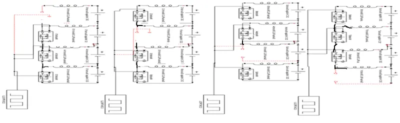
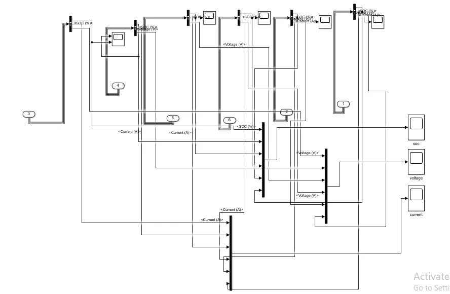
Active cell balancing simulation diagram
`
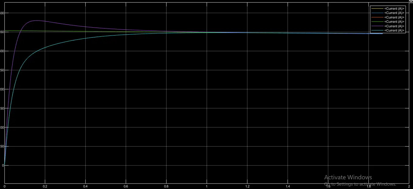
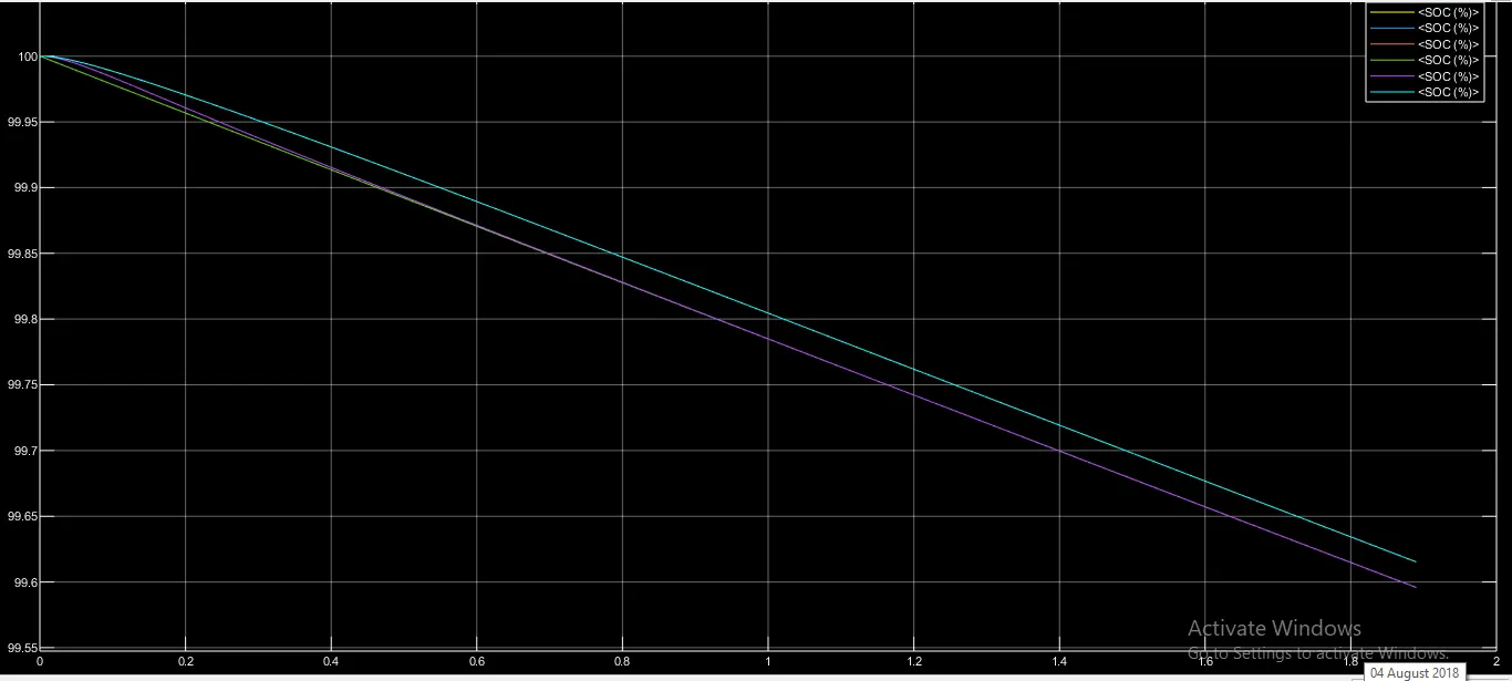
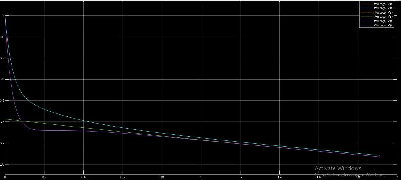
Results: