Week 6 Fuel cell powered vehicle model
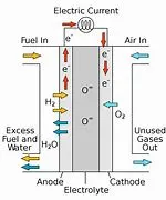
A fuel cell is an electrochemical cell that converts the chemical energy of a fuel (often hydrogen) and an oxidizing agent (often oxygen ) into electricity through a pair of redox reactions. Fuel cells are different from most batteries in requiring a continuous source of fuel and oxygen (usually from air) to sustain the chemical reaction, whereas in a battery the chemical energy usually comes from metals and their ions or oxides that are commonly already present in the battery, except in flow batteries.
Matlab model of a fuel cell
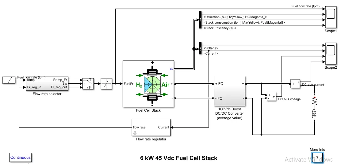
Description
The nominal Fuel Cell Stack voltage is 45Vdc and the nominal power is 6kW. The converter is loaded by an RL element of 6kW with a time constant of 1 sec. During the first 10 secs, the utilization of the hydrogen is constant to the nominal value (Uf_H2 = 99.56%) using a fuel flow rate regulator. After 10 secs, the flow rate regulator is bypassed and the rate of fuel is increased to the maximum value of 85 lpm in order to observe the variation in the stack voltage. That will affect the stack efficiency, the fuel consumption and the air consumption.
Fuel cell voltage, current, DC/DC converter voltage and DC/DC converter current signals are available on the Scope2. Fuel flow rate, Hydrogen and oxygen utilization, fuel and air consumption, and efficiency are available on the Scope1.
Simulation
At t = 0 s, the DC/DC converter applies 100Vdc to the RL load (the initial current of the load is 0A). The fuel utilization is set to the nominal value of 99.56%. The current increases to the value of 133A. The flow rate is automatically set in order to maintain the nominal fuel utilization. Observe the DC bus voltage (Scope2) which is very well regulated by the converter. The peak voltage of 122Vdc at the beginning of the simulation is caused by the transient state of the voltage regulator.
At t = 10 s, the fuel flow rate is increased from 50 liters per minute (lpm) to 85 lpm during 3.5 s reducing by doing so the hydrogen utilization. This causes an increasing of the Nernst voltage so the fuel cell current will decrease. Therefore the stack consumption and the efficiency will decrease (Scope1).
Scope results:
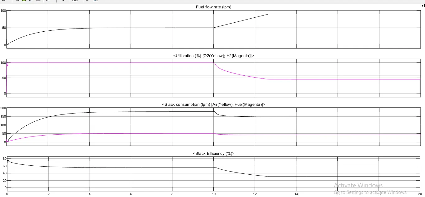
The fuel utilization is set to the nominal value of 99.56%.The flow rate is automatically set in order to maintain the nominal fuel utilization.At t = 10 s, the fuel flow rate is increased from 50 liters per minute (lpm) to 85 lpm during 3.5 s reducing by doing so the hydrogen utilization. This causes an increasing of the Nernst voltage so the fuel cell current will decrease. Therefore the stack consumption and the efficiency will decrease.
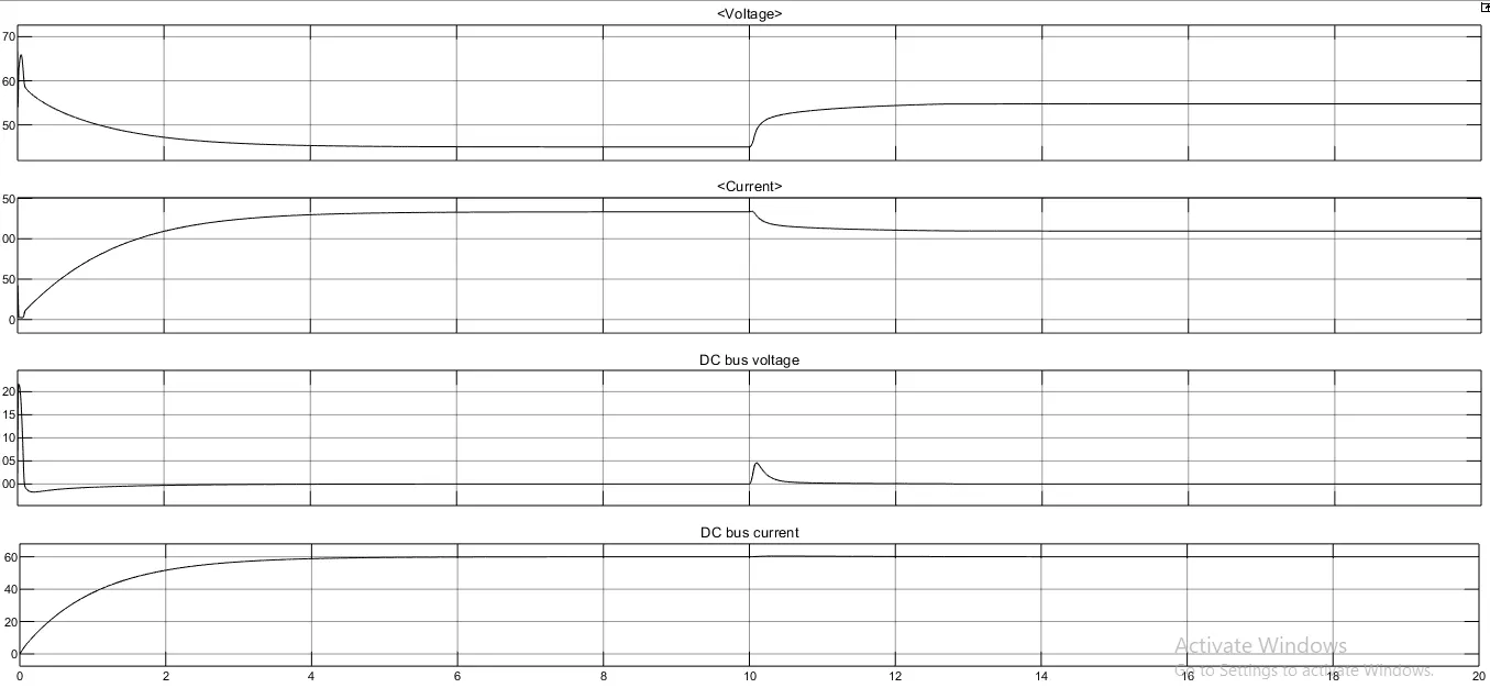
At t = 0 s, the DC/DC converter applies 100Vdc to the RL load (the initial current of the load is 0A).The current increases to the value of 133A.The peak voltage of 122Vdc at the beginning of the simulation is caused by the transient state of the voltage regulator.The DC bus voltage is very well regulated by the